Crown lock mechanism-installed timepiece

a technology of a crown lock and a timepiece, which is applied in the direction of normal winding, instruments, and horology, can solve the problem that the push force of the crown is not sufficiently transmitted to the corrector lever, and achieve the effect of simple operation and simple configuration

Active Publication Date: 2018-09-13
SEIKO INSTR INC
View PDF8 Cites 5 Cited by
  • Summary
  • Abstract
  • Description
  • Claims
  • Application Information

AI Technical Summary

Benefits of technology

[0022]According to this configuration, the regulator is formed from the groove portion and the ear portion of the lock portion. In this manner, the regulator can adopt a simple configuration.
[0023]In addition, the ear portion of the lock portion is fitted to the groove portion. In this manner, the simple configuration of the

Problems solved by technology

However, when the crown is locked, the screw portion of the winding stem pipe needs to interlock with the crown by pushing the crown against the biasing force of

Method used


Image

  • Crown lock mechanism-installed timepiece
  • Crown lock mechanism-installed timepiece
  • Crown lock mechanism-installed timepiece

Examples


Embodiment Construction

[0032]Hereinafter, an embodiment according to the present invention will be described with reference to the drawings.

[0033]First, a crown lock mechanism-installed timepiece according to the embodiment will be described.

[0034]In general, a machine body including a driving portion of a timepiece is referred to as a “movement”. A state of a finished product by attaching a dial and hands to the movement and placing the movement in a timepiece case (body) is referred to as a “complete assembly” of the timepiece.

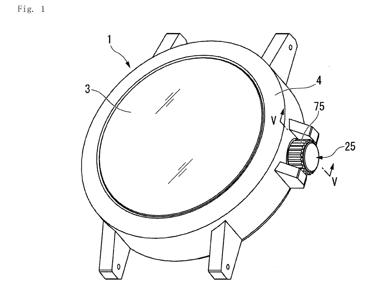
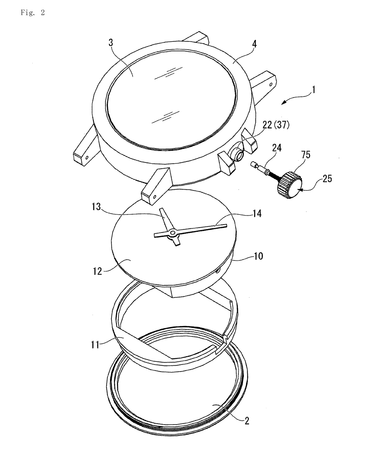
[0035]FIG. 1 is an external perspective view illustrating the timepiece according to the embodiment. FIG. 2 is an exploded perspective view illustrating the timepiece according to the embodiment. Hereinafter, a crown lock mechanism-installed timepiece 1 is abbreviated as a “timepiece 1”.

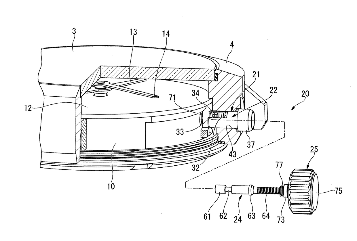
[0036]As illustrated in FIGS. 1 and 2, in the complete assembly of the timepiece 1, an interior of a timepiece case 4 having a case back 2 and a glass 3 is provided with a movement 10, an intermedi...


PUM


Abstract

There is provided a crown lock mechanism-installed timepiece which enables a lock mechanism to regulate an operation of a crown by using a simple operation. A crown lock mechanism includes a winding stem, a crown, a lock screw ring, an extrusion spring, and a regulator. The winding stem is connected to a corrector lever of a movement. The crown is fixed to the winding stem. The crown is capable of engaging with the lock screw ring, and the crown is supported by the lock screw ring so as to be movable in an axial direction. The extrusion spring biases the lock screw spring toward the crown. The regulator regulates the lock screw ring to be located at a predetermined position against a biasing force of the extrusion spring, and holds the crown engaging with the lock screw ring so as to stay at a normal hand operation position.

Description

RELATED APPLICATIONS[0001]This application claims priority under 35 U.S.C. § 119 to Japanese Patent Application No. 2017-047502 filed on Mar. 13, 2017, the entire content of which is hereby incorporated by reference.BACKGROUND OF THE INVENTION1. Field of the Invention[0002]The present invention relates to a crown lock mechanism-installed timepiece.2. Description of Related Art[0003]A timepiece is known which includes a crown pipe connected to a winding stem so as to be movable in an axial direction, a crown attached to the crown pipe, and an elastic member interposed between the winding stem and the crown. A biasing force of the elastic member is applied to the winding stem and the crown, thereby suppressing rattling of the crown.[0004]When the timepiece is switched to a time correction mode, the crown unscrewed and decoupled (disengaged) from a screw portion of the winding stem pipe is pulled out to a time correction position. On the other hand, when the crown is held in a normal h...

Claims


Application Information

Patent Timeline
IPC IPC(8): G04B3/04
CPCG04B3/043G04B3/041G04B3/046G04B37/04
Inventor IGUCHI, KATSUNOBU
Owner SEIKO INSTR INC
Why Eureka
Try Eureka