Lighting device and method for manufacturing a lighting device

a technology of lighting devices and manufacturing methods, applied in the direction of lighting, decorative arts, protective devices, etc., can solve the problems of significant cost factors for injection moulding, and achieve the effects of simple operation, simple structure and reliable us

Active Publication Date: 2018-12-27
TEKNOWARE
View PDF6 Cites 0 Cited by
  • Summary
  • Abstract
  • Description
  • Claims
  • Application Information

AI Technical Summary

Benefits of technology

[0008]The advantage of the lighting device according to the invention is that it is structurally simple and reliable. A suitable curve may be provided for the lighting device by bending the aluminium profile or injection moulding the body to a suitable shape. The tube used as the cover element does not need any fastening elements, but has a round profile. The cover element is thus particularly advantageous in terms of costs and easy to install to the body. No moulds or specific tools are required for manufacturing the cover element. The manufacture of the aluminium profile used as the body element and its bending to a suitable shape are also simple operations, and the same applies to the manufacture of the body by injection moulding.

Problems solved by technology

The problem in providing curved lighting devices specifically relates to the challenges of manufacturing the cover.
The curved cover may be formed by injection moulding, but the moulds used for injection moulding constitute a significant cost factor, especially if a single lighting device or just a few lighting devices are made to order.

Method used


Image

  • Lighting device and method for manufacturing a lighting device
  • Lighting device and method for manufacturing a lighting device
  • Lighting device and method for manufacturing a lighting device

Examples


Embodiment Construction

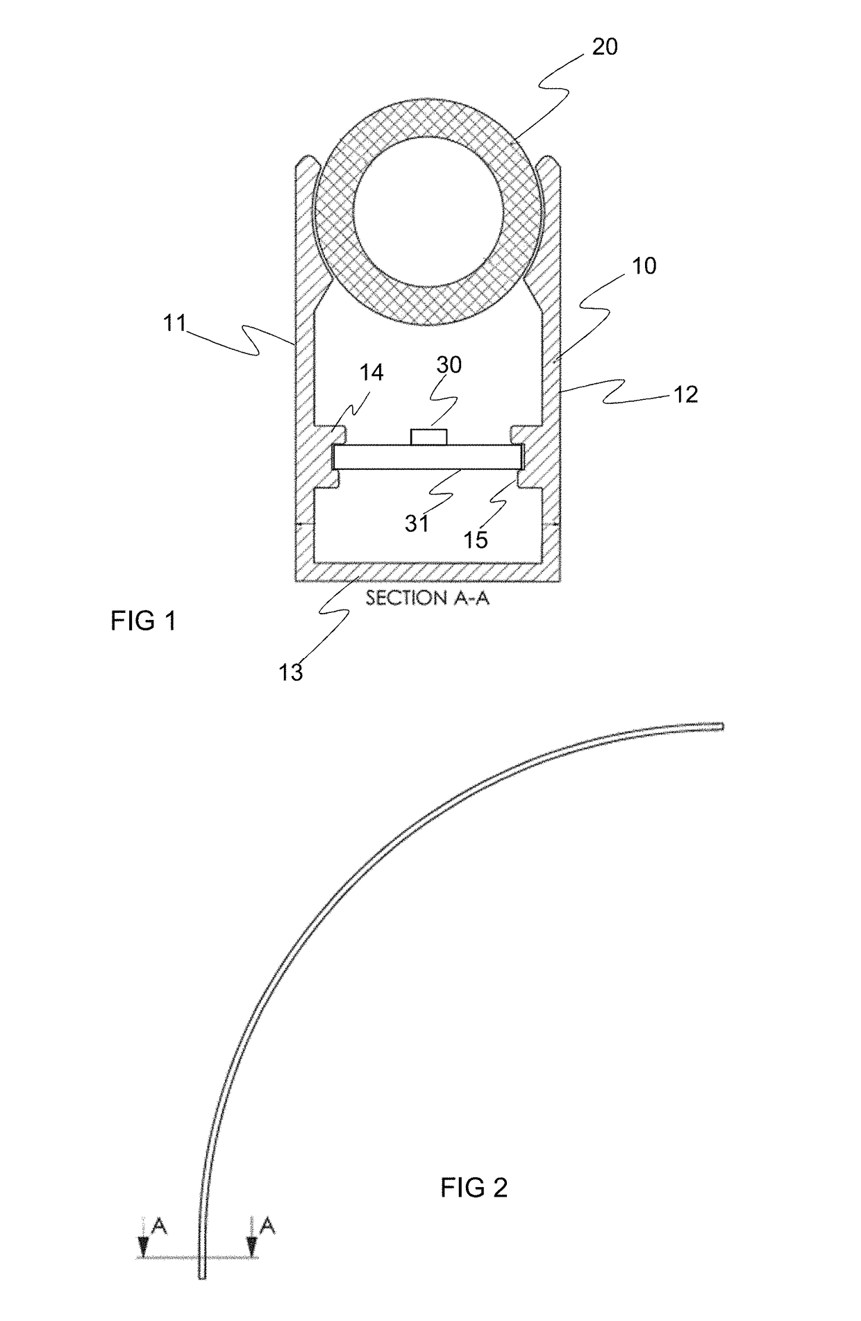
[0017]FIG. 1 is a cross-sectional view of a lighting device according to one embodiment of the invention. The lighting device of the invention is elongated, and the body of the lighting device is manufactured, for example, from an aluminium profile, i.e. extruded aluminium, or injection moulded plastic. FIG. 1 shows an example of the body of the lighting device in a basic form of a U-shape.

[0018]The lighting device of FIG. 1 comprises a body 10, a cover 20, and at least one light source 30. The body of the lighting device further comprises a bottom 13 forming a plane, and walls 11, 12 extending from the bottom with open edges. The body of the elongated lighting device, the bottom of the body, and the walls are also elongated, i.e. the U-shaped profile of the lighting device extends along the full extent of the lighting device. The walls 11, 12 shown in the profile of FIG. 1 thus extend in the longitudinal direction of the lighting device, and the walls have inner and outer surfaces....


PUM


Abstract

A lighting device and a method for manufacturing a lighting device, the lighting device comprising an elongated body (10), a cover (20), and one or more light sources (30). The body (10) of the lighting device comprises a bottom (13) and walls (11, 12) extending from the bottom and having open edges, whereby the cover (20) of the lighting device is formed from a light transmitting plastic material tube arranged between the open edges of said walls (11, 12) at a distance from the bottom (13), the one or more light sources (30) being located in a space delimited by the body (10) and the cover (20) of the lighting device, the body of the lighting device comprising at least one curved portion to provide a curved lighting device.

Description

FIELD OF THE INVENTION[0001]The invention relates to lighting devices, and specifically to elongated lighting device structures having a curved shape.BACKGROUND OF THE INVENTION[0002]An elongated lighting device that may be bent to adapt to the shape of a structure, for example, is needed for many purposes. For example, such lighting devices may be used as a detail of interior decoration, or as an extension of an otherwise straight line of lights. Elongated lighting devices are usually decorative lights, fixedly installed to a wall, a vertical element or a ceiling of a structure.[0003]Lighting devices typically include three basic components: a body, a light source and a light diffusing cover element. One or more light sources are disposed between the body and the cover element, whereby the lighting device is a closed lighting device. In fixedly installed lighting devices, the body is fastened to a structure, such as a wall, a ceiling, or the like. The light sources between the body...

Claims


Application Information

Patent Timeline
Patent Type & Authority Applications(United States)
IPC IPC(8): F21S4/26F21S8/00F21V8/00G09F13/22
CPCF21S4/26F21S8/03G02B6/0073G09F13/22F21Y2115/10F21Y2103/10F21V3/02F21V15/013F21V19/0045F21W2121/00F21S4/28F21Y2103/30B29D11/00F21V3/04F21S4/22
Inventor SILTANEN, OSKARI
Owner TEKNOWARE
Why Eureka
Try Eureka