

Method, system, and program for monitoring system components
a monitoring system and component technology, applied in the field of system and program monitoring system components, can solve problems such as system generation of excessive notifications
- Summary
- Abstract
- Description
- Claims
- Application Information
AI Technical Summary
Benefits of technology
Problems solved by technology
Method used
Image

Examples
Embodiment Construction
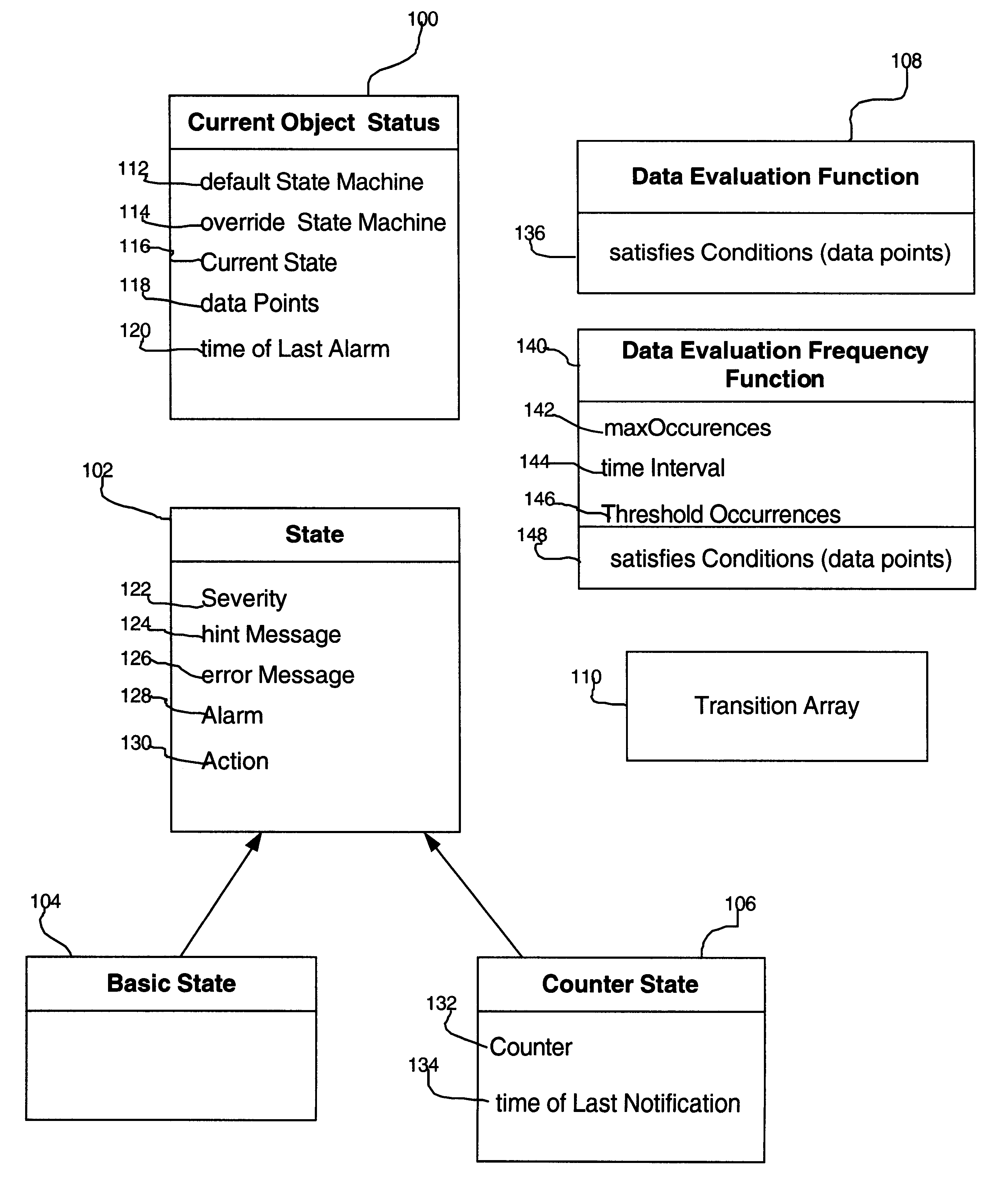
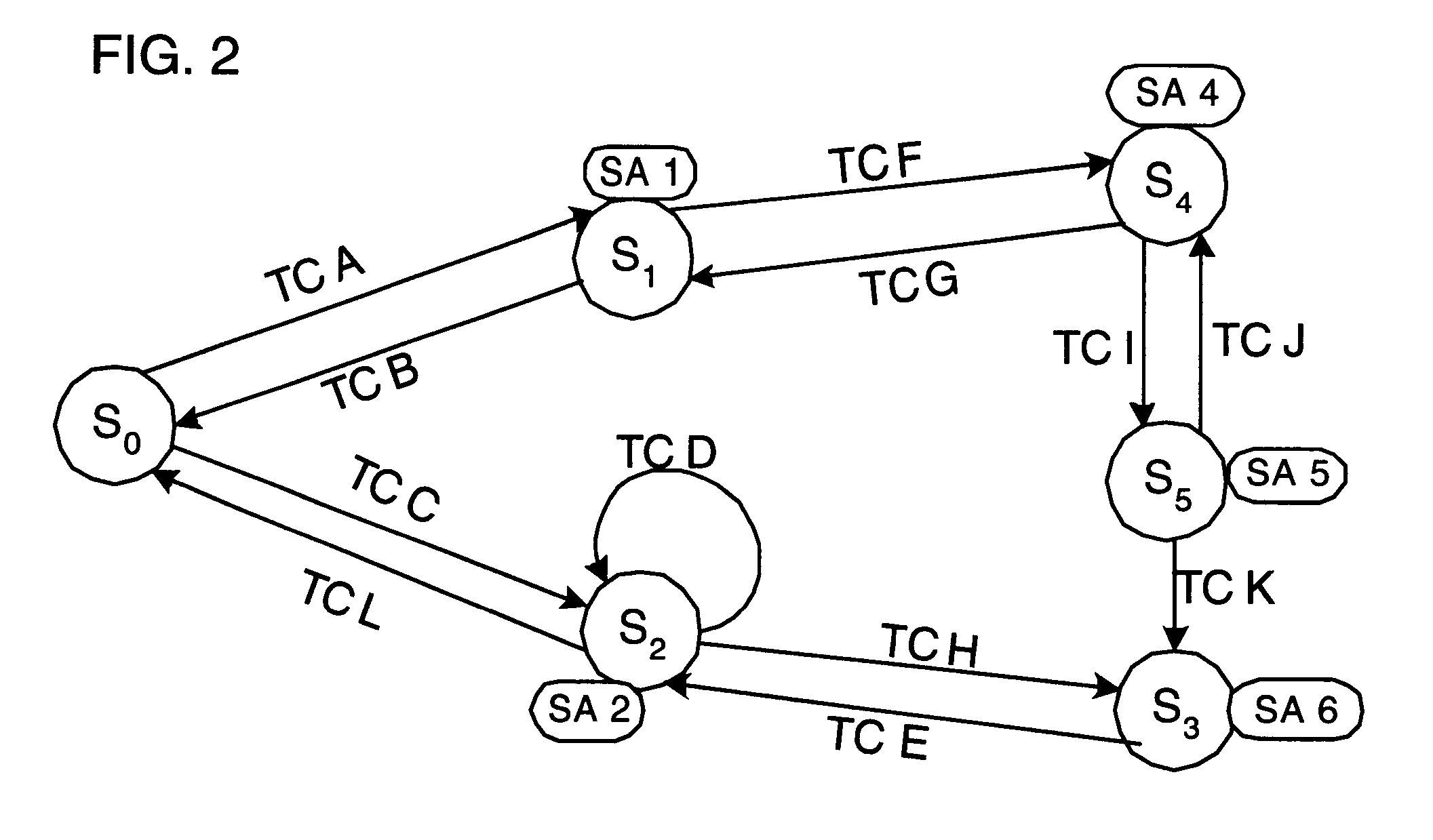
Provided is a method, system, program, and data structure for deriving state information concerning a monitored system component A status object is provided including information on a current state of the monitored system component. There are a plurality of states associated with the monitored system component, wherein each state is capable of having a state action and at least one transition condition associated with a transition state. A measured system parameter is received and a determination is made as to whether the received measured system parameter satisfies one transition condition associated with the current state indicated in the status object. If the received system parameter satisfies one transition condition, then the state action associated with the transition state associated with the satisfied transition condition is performed. The current state is set to the transition state in the status object.
In further implementations, if the transition state associated with th...
PUM
 Abstract
Description
Claims
Application Information