Light card

a technology of light cards and light sources, applied in the field of light devices, can solve the problems of premature failure of leds, undesirable switching functions, and general deficiency of known light cards in the switching mechanism used,

Inactive Publication Date: 2006-05-02
WATERS
View PDF20 Cites 8 Cited by
  • Summary
  • Abstract
  • Description
  • Claims
  • Application Information

AI Technical Summary

Benefits of technology

[0005]In accordance with the invention, a light card is provided having a switch bar mounted thereto that is operable for providing power to an LED carried by the card. The switch bar is advantageous in that it can be operated independent of the LED and the body of the card. In other words, operation of the switch bar need not require that one of the leads of an LED be bent and / or a portion of the body of the card be deflected for turning the LED light on. Accordingly, the switch bar provides a much more robust switching mechanism as it can be specifically arranged and configured to allow for a user to bend or deflect the bar during switching operations without generating undue fatigue and damage to the LED or potentially the card body itself.
[0008]In another aspect, the light card includes an LED and a conductive switch bar that is distinct from the LED. The switch bar has an elongate and substantially thin, flat configuration that extends along the card body and is of flexible, shape-retentive material. The switch bar has one end fixed to the card body with the other end cantilevered from the fixed end. The cantilevered end and thin, flat configuration of the switch bar allows for easy pushing of the switch bar cantilevered end for energizing the LED. In other words, the cantilevered end provides a lever arm for the switch bar so that it requires a fairly low force for bending the switch bar at the cantilevered end thereof. In addition, the flat configuration provides a greater surface area for engagement therewith so that a user is less likely to miss the user engageable portion of the switching mechanism when attempting to turn the light on.

Problems solved by technology

However, known light cards are generally deficient in the switching mechanisms utilized to selectively power the lights carried thereby.
As is apparent, both of these features are undesirable for the switching function in which they are implemented as it is anticipated that the light switch may be activated thousands of times over the life of a light card.
As such, this constant bending of the LED lead wire may ultimately cause premature failure of the LED.
Similarly, where the main wall of the card also is thinned and constantly bent for switching the light on, there is the possibility that the thinned wall will fail over repeated cycling.
An additional problem with light cards employing LEDs of the type described above is that they typically have to be used along the edge of the card projecting light out from one of the side edges thereof.
This is due to their large space requirements relative to the size of the card, and its thickness between the two main faces thereof in particular.

Method used


Image

  • Light card
  • Light card
  • Light card

Examples


Embodiment Construction

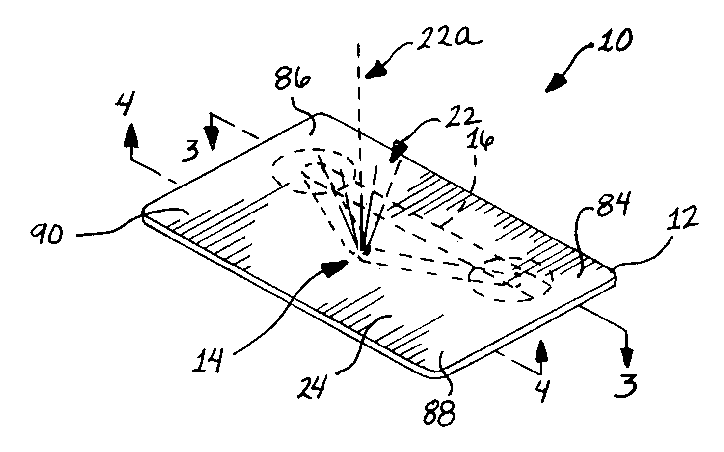
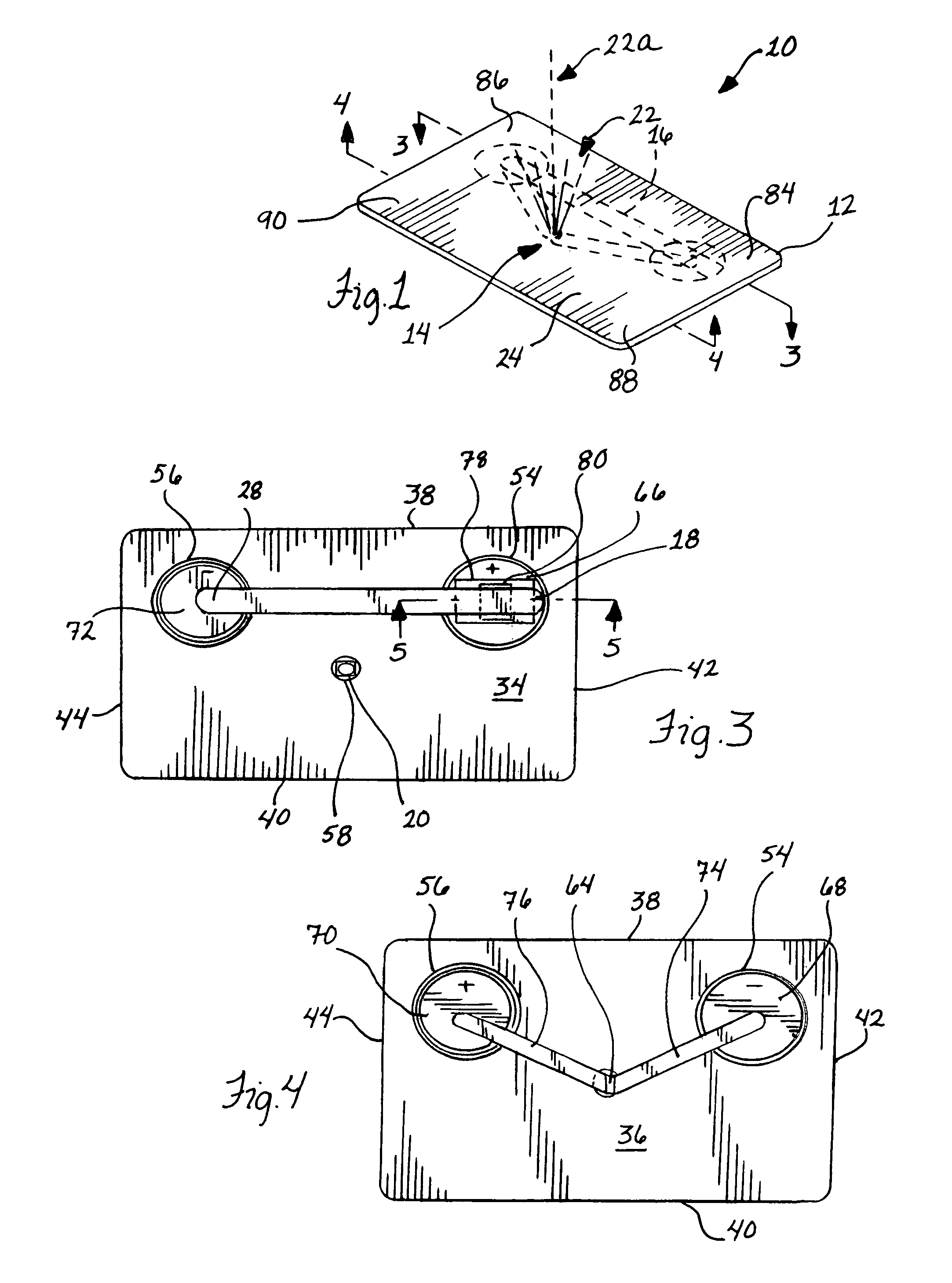
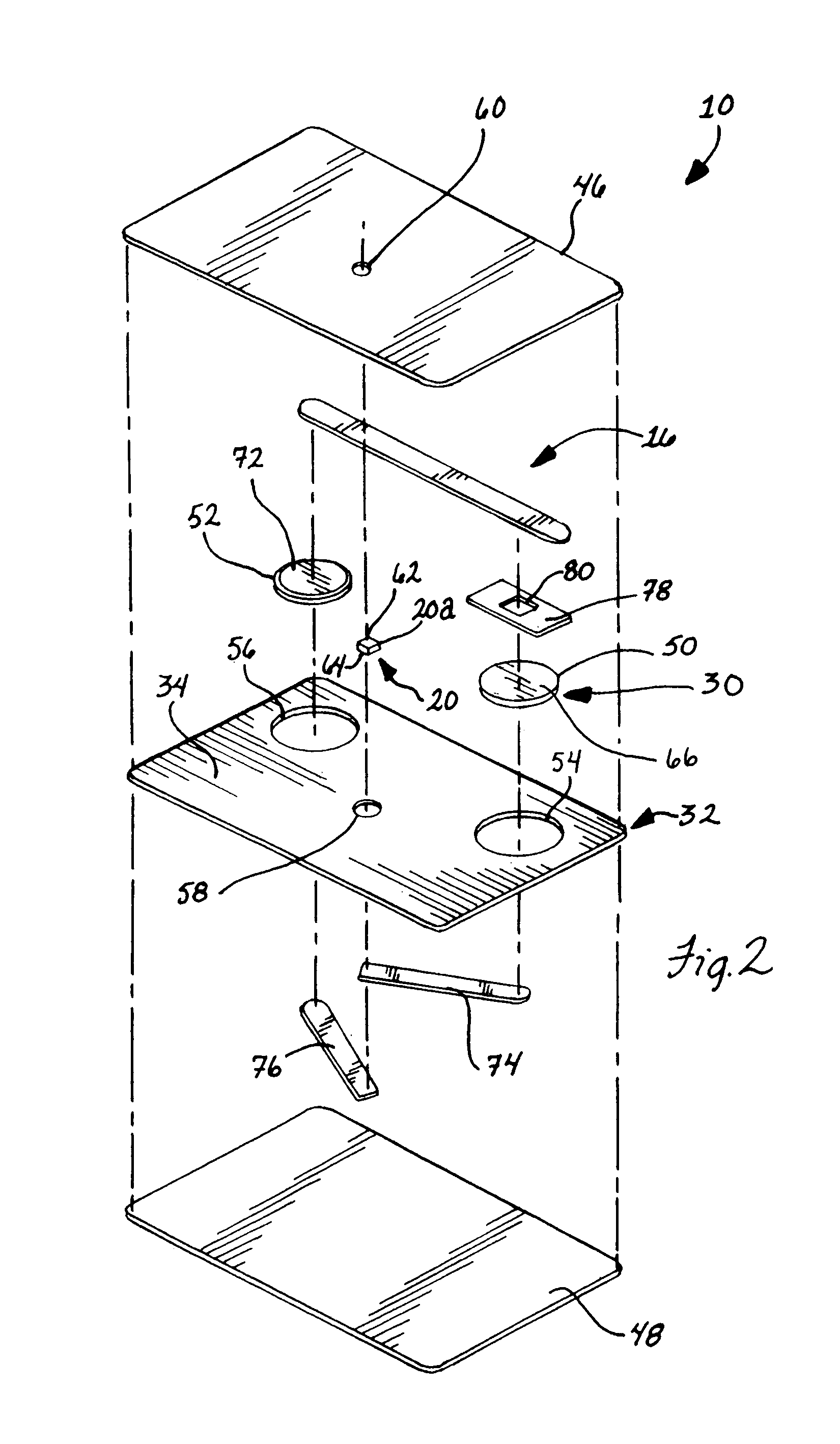
[0023]In FIGS. 1 and 2, a light card 10 is shown including a card member 12 that carries a light source 14 and a switch bar 16 that is operable to energize the light source 14. It is preferred that the switch bar 16 be independent or distinct from the light source 14 so that its operation to perform the switching function thereof does not mechanically affect the components of the light source 14 and thus is solely operable to provide power to or remove power from the light source 14. In addition, the switch bar 16 can be arranged and configured so that it is easy to engage and push the switch bar 16 and in particular end 18 (FIG. 3) thereof for flexing the bar 16 to energize the light source 14. In this regard, it is preferred that the switch bar 16 have an elongate and thin, flat strip configuration and be of a resilient, conductive metallic material. In this manner, the switch bar or strip 16 is designed to be robust and withstand flexing thereof over thousands switching cycles wi...


PUM


Abstract

A light card is provided having a switch bar that avoids the need to bend an LED lead for turning the LED light on. The light card can be implemented in a credit or debit card size, with a viewing lens, or used as a key ring holder.

Description

FIELD OF THE INVENTION[0001]The invention relates to lighting devices and, more particularly, to card members carrying lights thereon.BACKGROUND OF THE INVENTION[0002]Providing lights on thin card members advantageously provides compact and low profile lighting devices for users thereof. However, known light cards are generally deficient in the switching mechanisms utilized to selectively power the lights carried thereby. Generally, when employing LEDs that include elongate wire positive and negative leads extending therefrom, it is known that mechanical stress on the leads should be avoided. However, where such LEDs are employed with lighted cards, there are switching mechanisms thereof that have required that one of leads be bent each time the LED light is to be turned on (see U.S. Pat. No. 5,457,613 to Vandenbelt et al. and U.S. Pat. No. 6,070,990 to Dalton, et al.). In addition to the undue stress on the LED leads generated by the switching mechanisms taught by the '613 and '990...

Claims


Application Information

Patent Timeline
Patent Type & Authority Patents(United States)
IPC IPC(8): G06K21/00
CPCF21L4/027G06K19/077F21V33/0004F21Y2101/02F21Y2115/10
Inventor WATERS, MICHAEL
Owner WATERS
Why Eureka
Try Eureka