Cutting insert with helical geometry and holder therefor

a cutting insert and helical geometry technology, applied in the field of cutting inserts, can solve the problems of reducing the efficiency of chip removal

Inactive Publication Date: 2006-11-07
ALLIED MASCH & ENG CORP
View PDF19 Cites 27 Cited by
  • Summary
  • Abstract
  • Description
  • Claims
  • Application Information

AI Technical Summary

Benefits of technology

[0008]These and other objects of the invention are also provided by a drilling tool assembly comprising a holder having a first end, a second end, and a cylindrical drill portion between the first end and the second end, wherein the second end comprises a shank portion adapted to be fixedly attached in a drilling machine, wherein the first end comprises a holder slot having a bottom seating surface over at least a portion of the holder slot and at least one attachment arm positioned on each side of the holder slot, wherein each attachment arm has at least one aperture formed therein, and wherein the cylindrical drill portion has a first plurality of helical flutes formed therein, a drill insert comprising a drill insert body having a first drill insert end opposite a second drill insert end, a second plurality of helical flutes formed in the drill insert body and extending axially from the first drill insert end to the second drill insert end; a plurality of curved cutting edges formed at the interfaces of the second plurality of helical flutes and the first drill insert end of the drill insert body; and wherein the drill insert body includes at least two apertures, each aperture positioned through each helical flute and extending through the drill insert body to a generally planar attachment surface on an opposite side of the drill insert body, wherein the drill insert is removably secured to the holder by at least two fasteners, each fastener positioned through each helical flute of the second plurality of flutes and extending through the drill insert body into the aperture formed in each attachment arm of the holder.

Problems solved by technology

One problem with prior art spade-type cutting tools is that insert is typically configured as a flat blade and the holder is configured with a straight flute.
Even when used with flush channels through the holder, these types of drill assemblies are best suited for drilling shallow holes at relatively slower speeds due to their poor chip removal.
Attempts have been made in the prior art to combine the versatility and cost-effectiveness of the spade-type insert and holder with the benefits of helical flutes, however, these efforts have resulted in complex or inadequate blade retaining systems as well as complex shaped blades which negate the cost benefits of the replaceable blade insert.
In this prior art configuration, the chips are first transported by a straight portion resulting in loss of efficiency in removing chips and forcing a slower cutting speed for the tool.
If the point does not adequately conduct heat away from its cutting edges, the temperature buildup will “burn” the point and diminish the life of the drill bit.
However, these prior art inserts are apt to direct chips directly into the clamp arms of the holder during operation of the tool.
The chips impacting against the clamp arms erode and wear the clamp arms.
This chip erosion of the clamp arms significantly reduces the life of the holder.

Method used


Image

  • Cutting insert with helical geometry and holder therefor
  • Cutting insert with helical geometry and holder therefor
  • Cutting insert with helical geometry and holder therefor

Examples


Embodiment Construction

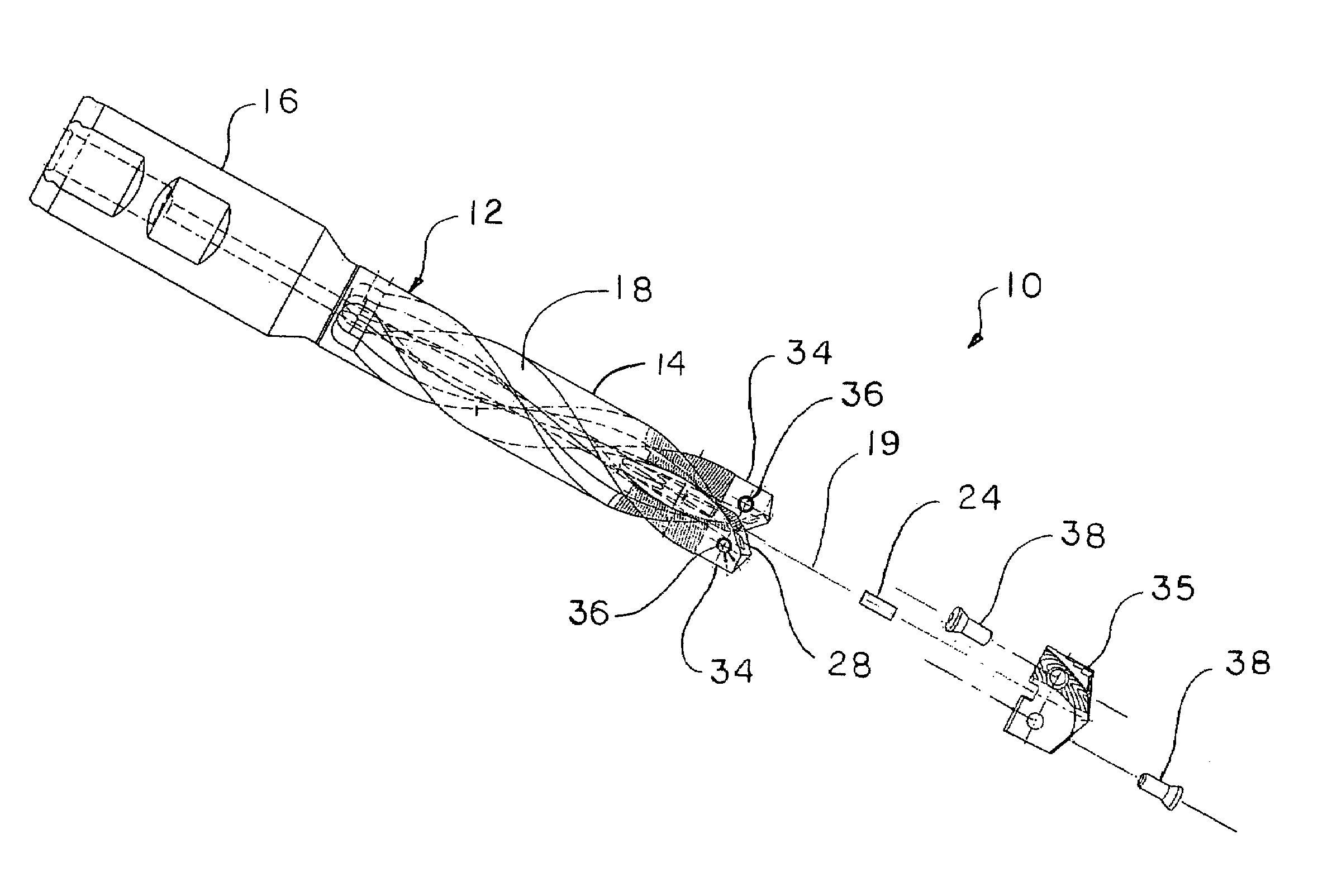
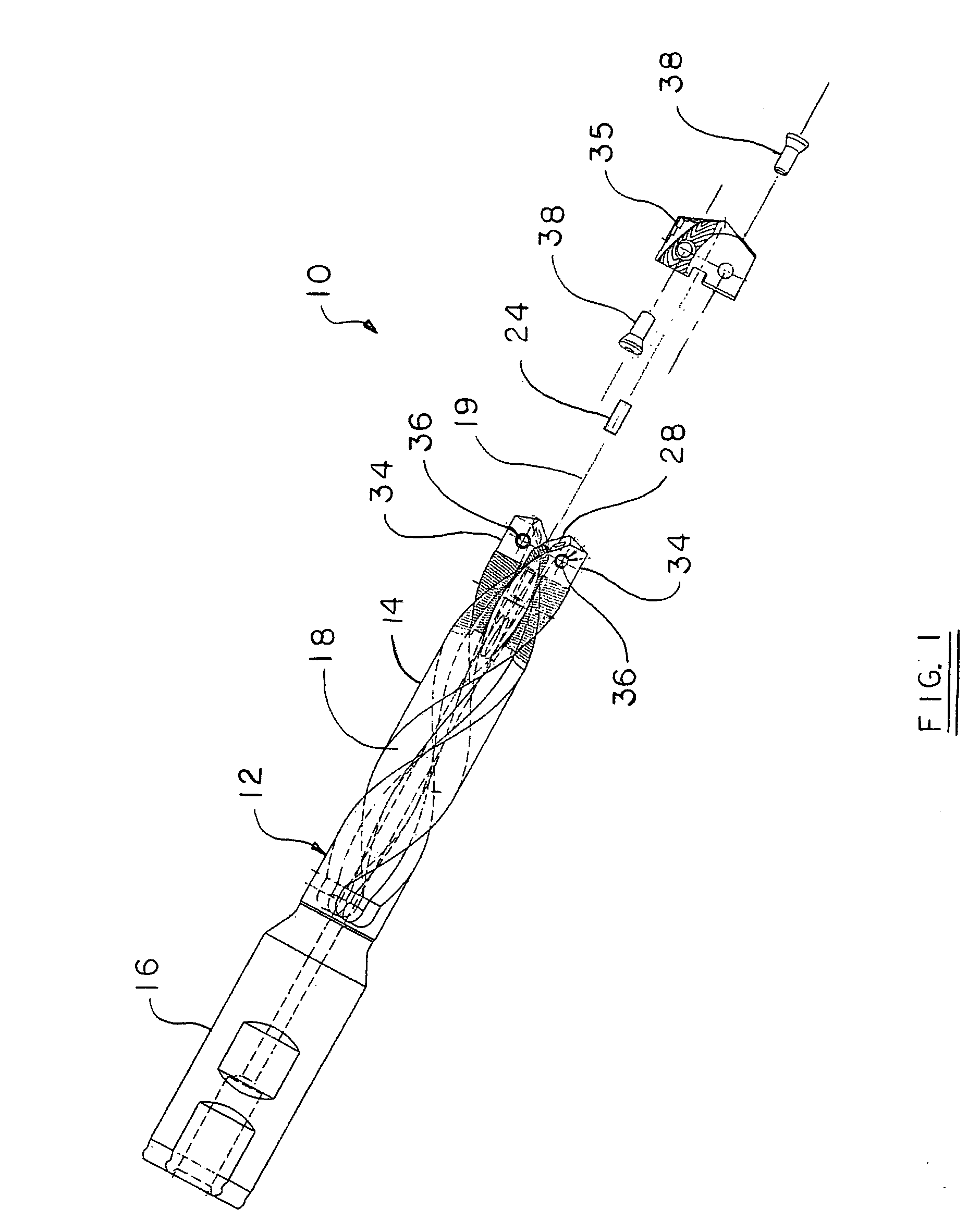
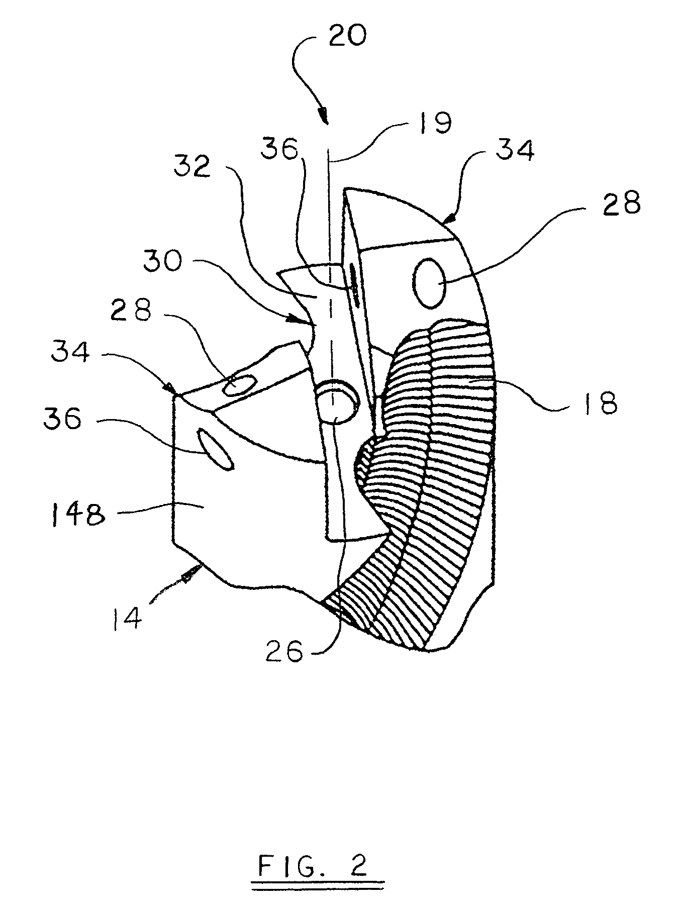
[0017]Turning now to an embodiment of the invention, FIG. 1 illustrates a drill tool assembly 10 generally indicated in an exploded view. Drill tool assembly 10 comprises a holder 12, which has a drill body 14 and shank 16 associated therewith. The body 14 comprises a pair of helical flutes 18 formed therein. Holder 12 has, in general, a cylindrical shape with a holder end 20 opposite the shank 16 which is configured to securely support a drill insert 35. As shown in FIG. 2, the holder end 20 has a clamping or holder slot 30, which may extend across the entire diameter of the holder end 20 or, at least, over a center portion thereof at the general location of the rotational axis 19 of holder 12. The holder slot 30 has a bottom wall 32 positioned in substantially perpendicular orientation relative to the rotational axis 19 of the holder 12. In one embodiment, the assembly 10 may further include a locating boss or dowel pin 24 (see FIG. 1), which is positioned precisely with respect t...


PUM

PropertyMeasurementUnit
thicknessaaaaaaaaaa
rake angleaaaaaaaaaa
radiusaaaaaaaaaa

Abstract

A cutting tool insert and holder therefore, the drill insert having a helical geometry corresponding to helical flutes in a drill body holder which enable the drill tool assembly to more efficiently remove chips from a hole during operation, the drill insert comprising a drill insert body having a first end opposite a second end, a plurality of helical flutes formed in the drill insert body, a plurality of cutting edges formed at the interfaces of the plurality of helical flutes and the first end of the drill insert body, and an aperture formed in each helical flute.

Description

TECHNICAL FIELD[0001]The invention relates generally to a cutting insert to be placed into a tool holder for boring holes into metals. More specifically, the invention relates to a cutting tool insert having a helical geometry corresponding to helical flutes in a drill body holder which enables the drill tool assembly to more efficiently remove chips from a hole during operation.BACKGROUND OF THE INVENTION[0002]Drilling systems are frequently used to provide cylindrical holes in metallic workpieces. The cutting or boring action of the drill system may be carried out by an elongated, substantially cylindrical drilling tool, such as a combination of a tool holder and a drill insert, which is selectively attached thereto such as the type commonly referred to as a spade-type drill. Such an arrangement may then be used in an application wherein one end of the tool holder is securely mounted in a driving apparatus, which rotates the holder about its longitudinal axis. At the opposite end ...

Claims


Application Information

Patent Timeline
Patent Type & Authority Patents(United States)
IPC IPC(8): B23B51/00B23B51/02B23D77/00B27G15/00
CPCB23B51/0009B23B2251/082B23B2251/14B23B2251/18B23B2251/406B23B2251/408Y10T408/9097Y10S408/713Y10T408/9098Y10T408/909Y10T408/90993B23B2251/50B23B51/00035B23B51/02B23B51/00
Inventor STOKEY, STEVEN R.JACKSON, MARTIN ALANNUZZI, JOSEPH P.MAST, WENDELL E.
Owner ALLIED MASCH & ENG CORP
Why Eureka
Try Eureka