Lock barrel and a driving part for the same

a technology of driving parts and locks, applied in the field of locks, can solve the problems of difficult manufacture and maintenance, difficulty in manufacturing such locks, and difficulty in intrusion of illegal tools, and achieve the effect of effectively smaller channels

Inactive Publication Date: 2008-04-08
CHAO SHENG HO +1
View PDF16 Cites 6 Cited by
  • Summary
  • Abstract
  • Description
  • Claims
  • Application Information

AI Technical Summary

Benefits of technology

[0006]Accordingly, the primary objective of the present invention is to provide a lock barrel and a driving part for the same wherein the key channels have a plurality of transversely movable parts for making the channels effectively smaller, which can prevent the manufacturing problem of making lock barrel of small key channel.
[0007]The secondary objective of the present invention is to provide a lock barrel having two key channels, therefore increasing the difficulty of opening the lock illegally.
[0008]To achieve above object, the present invention provides a lock barrel and a driving part for the same. The present invention comprises an outer shell with a longitudinal receptacle; a central shaft disposed in said outer shell capable of rotating relative to said outer shell, said central shaft further comprising an outer wall and a plurality of coaxial key channels, said central shaft having one end open for the insertion of a driving part; and a plurality of movable parts slidably housed in respective gateways transverse to said shaft and connecting said key channels, each of said movable parts capable of being driving by said inserted driving part to move from a first position to a second position.
[0009]The lock barrel of the present invention utilizes driving part (key shaft) having arced cross sections for fitting the semi-circular key channels. A plurality of pin sets can be added in the key channels for reducing working space for a thief.

Problems solved by technology

Even locks with electronic devices, such as mechanisms for finger print and voice recognition, are invented, they are expensive to manufacture and maintain.
One effective way of enhancing the antitheft function of a lock barrel is using a non-straight key channel, therefore making the intrusion of an illegal tool difficult.
However, it is difficult to manufacture such a lock, since the key must be foldable; special materials should be used to make the key.
However, the production of this kind of key barrels concerns the building of molds of much better precision, which is expensive.
Further, the key associated with a lock barrel of small key channel is usually structurally weak.

Method used


Image

  • Lock barrel and a driving part for the same
  • Lock barrel and a driving part for the same
  • Lock barrel and a driving part for the same

Examples


Embodiment Construction

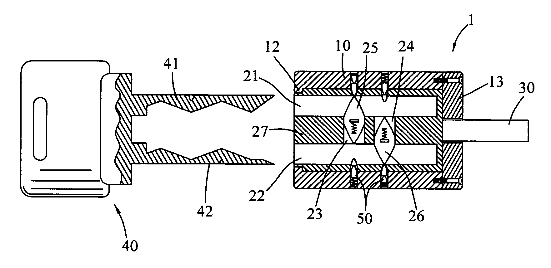
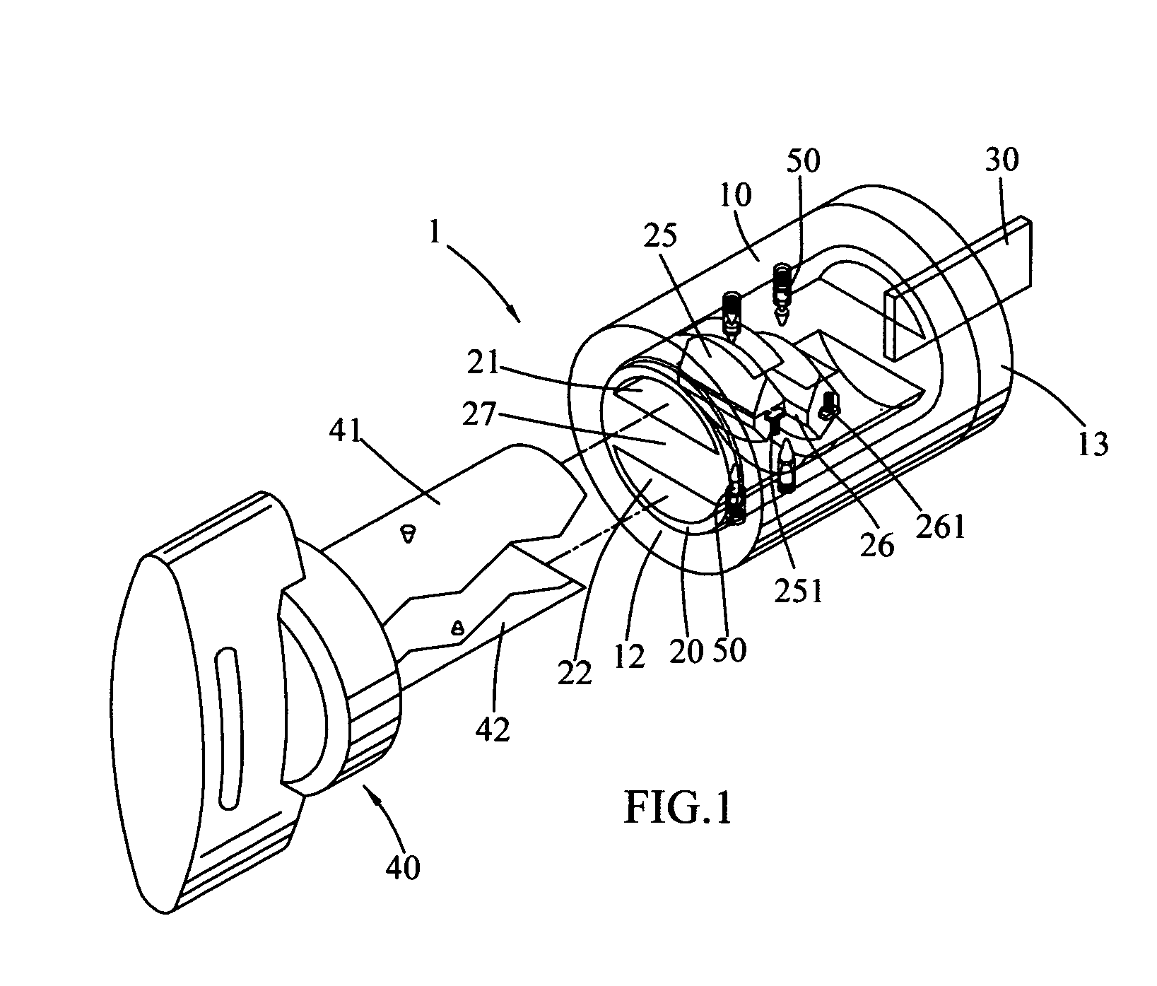
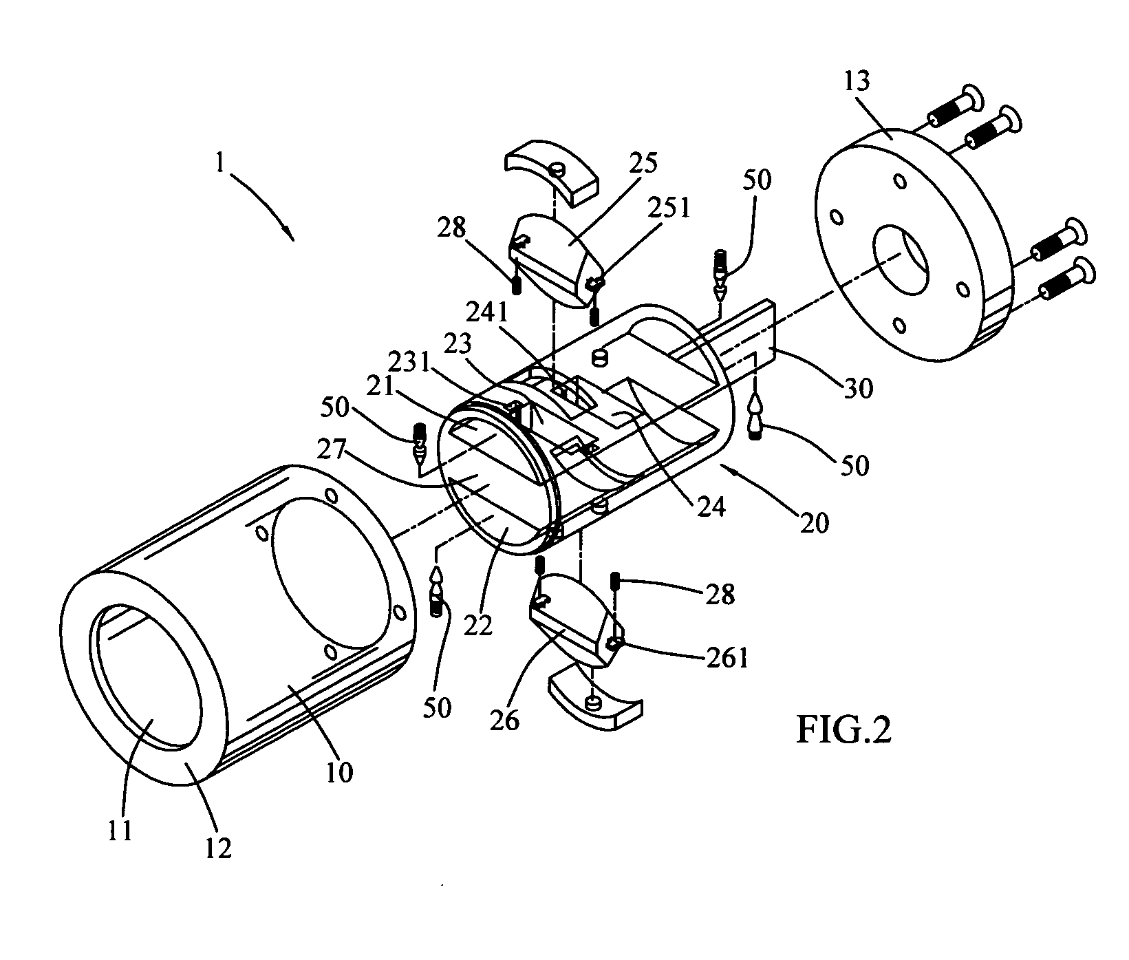
[0016]Referring to FIGS. 1 and 2, a lock barrel 1 of the present invention according to the present invention comprises a cylindrical lock shell 10 and an coaxial shaft 20 rotationally contained within an central receptacle 11, whereby the shaft 20 will rotate relative to the lock shell 10. The open end of the lock shell 10 is provided with a flange 12 for preventing the shaft 20 from sliding out. The other end of the lock shell 10 is sealed by an end cover 13 whereon a passive beam 30 is mounted for controlling a lock tongue.

[0017]Referring to FIGS. 3 and 3A, the shaft 20 further includes an outer surface and an inner space portioned by a divider slab 27 of predetermined thickness, whereby the inner space will he divided into two semi-circular first and second key channels 21, 22. There are a first gateway 23 and a second gateway 24 penetrating the divider slab 27 connecting the first key channel 21 and the second key channel 22. The first gateway 23 is close to the flange 12. Each...


PUM


Abstract

A lock barrel and a driving part for the same comprises a plurality of key channels for the insertion o the driving part (key) and a plurality of transverse gateways for housing movable parts, which will bulge into the key channels for making the channels effectively small and therefore shielding them from illegally intruded tools.

Description

FIELD OF THE INVENTION[0001]The present invention relates to locks, more particularly to a lock barrel that needs to be opened by a special key.BACKGROUND OF THE INVENTION[0002]Lock has evolved for hundred years, aiming at enhancing its antitheft function. Even locks with electronic devices, such as mechanisms for finger print and voice recognition, are invented, they are expensive to manufacture and maintain. Therefore, mechanical locks are still the main stream.[0003]The lock barrel of a lock has a set of pins and associated recoil springs. A key to the lock can switch the positions of the pins, achieving the purpose of opening the lock. To open the lock without a key, a slim, elongated tool is inserted into the key channel in the lock barrel for activating the pins.[0004]In other words, a lock barrel is the core mechanism of a lock and where an antitheft innovation should be applied to. One effective way of enhancing the antitheft function of a lock barrel is using a non-straight...

Claims


Application Information

Patent Timeline
Patent Type & Authority Patents(United States)
IPC IPC(8): E05B27/06
CPCE05B27/0035E05B19/007Y10T70/7836Y10T70/787Y10T70/7565Y10T70/7599
Inventor CHAO, SHENG-HOHUANG, CHANG-TUNG
Owner CHAO SHENG HO
Why Eureka
Try Eureka