Mounting assembly of computer enclosure

a computer enclosure and mounting assembly technology, applied in the direction of carpet fasteners, electrical apparatus casings/cabinets/drawers, instruments, etc., can solve the problems of inability to remove the panel, limited expansion function of the computer enclosure, inconvenience for computer users in operation in incommodious computer enclosures

Inactive Publication Date: 2008-11-11
HONG FU JIN PRECISION IND (SHENZHEN) CO LTD +1
View PDF13 Cites 27 Cited by
  • Summary
  • Abstract
  • Description
  • Claims
  • Application Information

AI Technical Summary

Benefits of technology

[0004]With the advancement of science and technology, computers are widely used in every walk of life. More and more computer users hope to detach a computer enclosure conveniently for checking malfunction of hardware and repairing interior components of a computer. However, nowadays, with the tide of miniature computer enclosure, computer users are of inconvenience in operation in incommodious computer enclosure. In addition, an expanded function of the computer enclosure is also limited. Therefore, it is required that a front panel should be demounted conveniently from a chassis. A typical mounting assembly is that a front panel is directly riveted to a chassis or a front panel is integrally molded with a chassis. However, the front panel cannot be detached when necessary for installation or removal of other electronic components, which probably causes damage of the electronic components due to insufficient room.

Problems solved by technology

However, nowadays, with the tide of miniature computer enclosure, computer users are of inconvenience in operation in incommodious computer enclosure.
In addition, an expanded function of the computer enclosure is also limited.
However, the front panel cannot be detached when necessary for installation or removal of other electronic components, which probably causes damage of the electronic components due to insufficient room.
Generally, that the front panel can not be detached can bring much trouble when computer users assemble or disassemble electronic components in incommodious computer enclosure.
This also inevitably increases the assembly time.
As a result, production efficiency is reduced to a certain degree.

Method used


Image

  • Mounting assembly of computer enclosure
  • Mounting assembly of computer enclosure
  • Mounting assembly of computer enclosure

Examples


Embodiment Construction

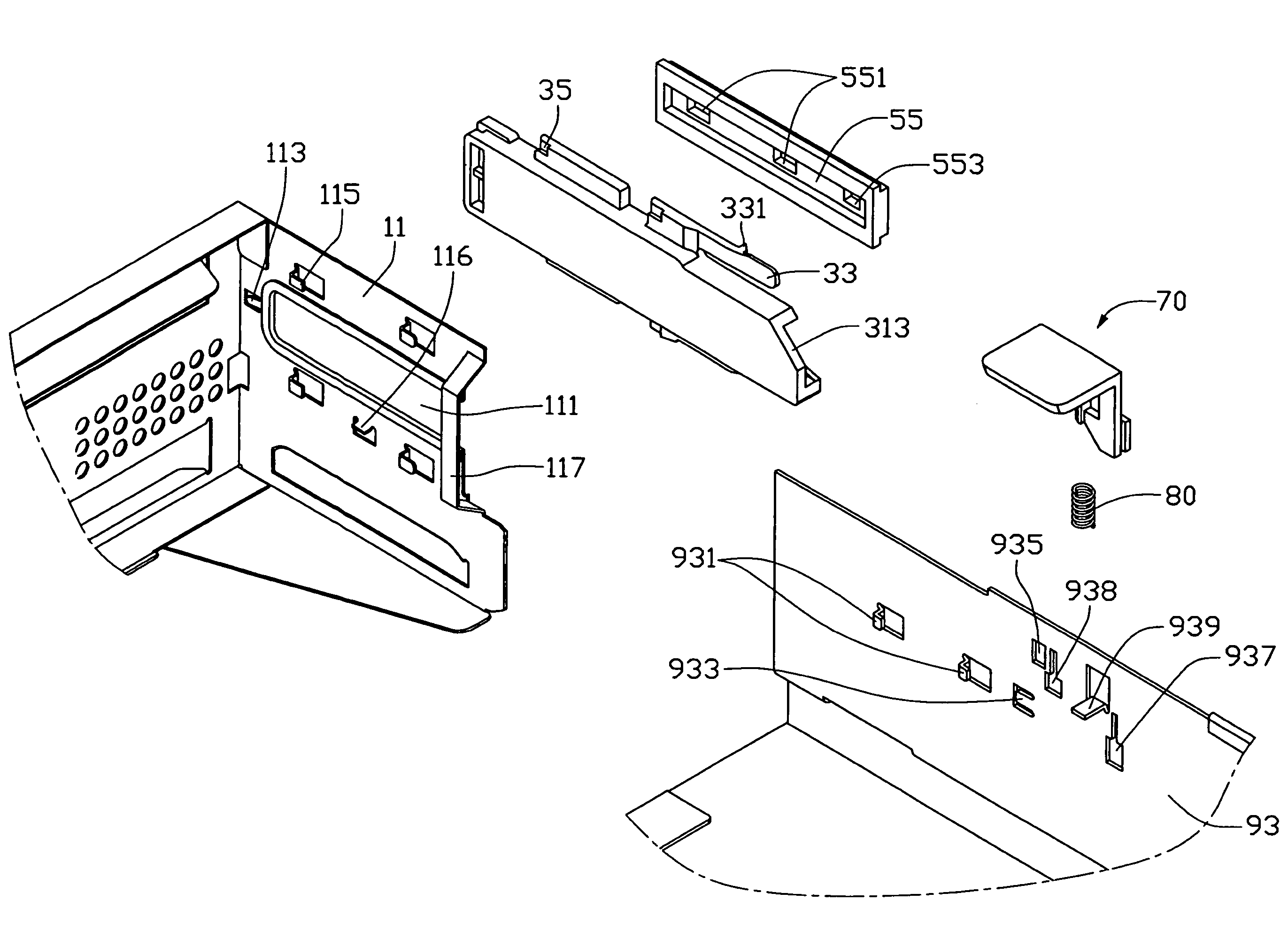
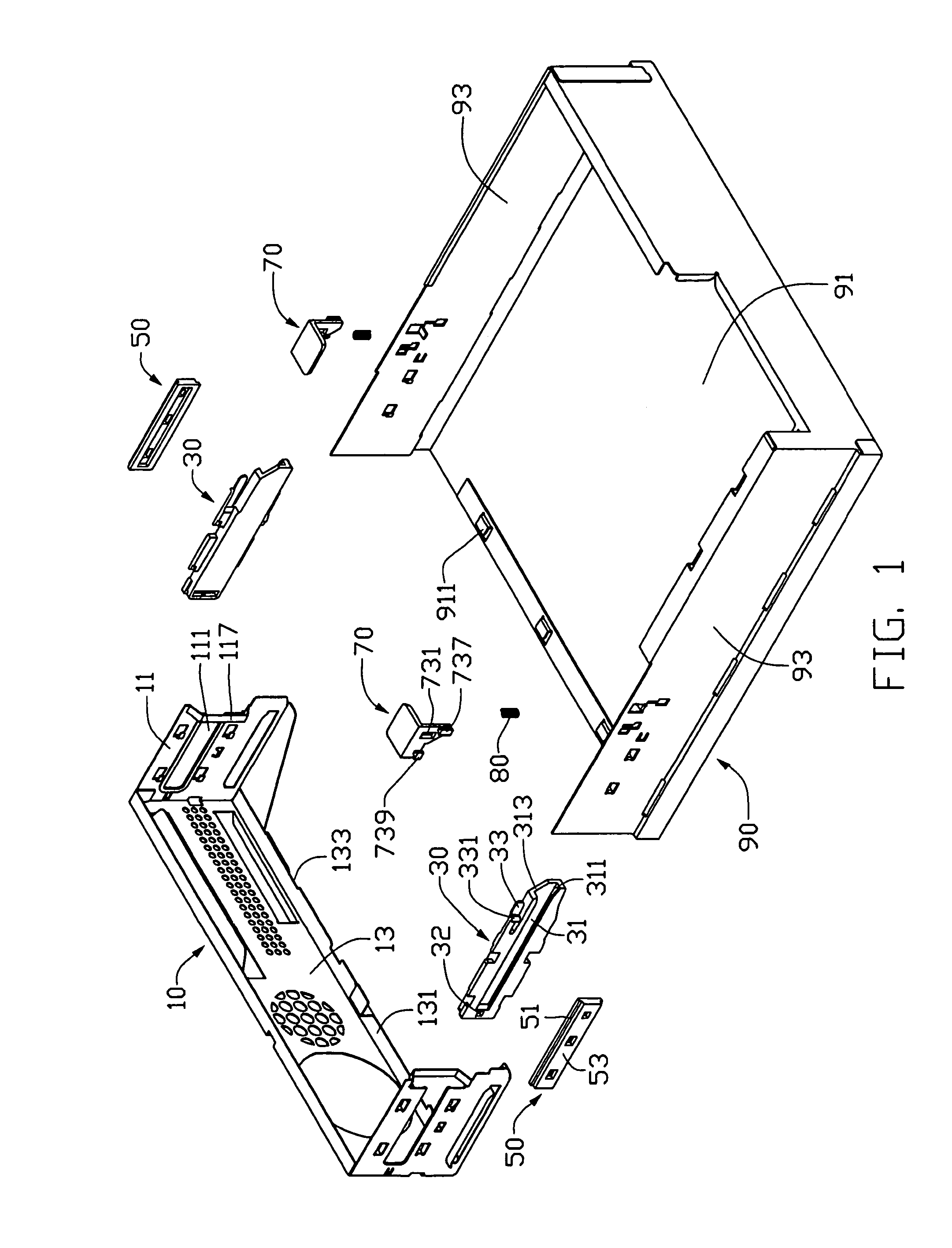
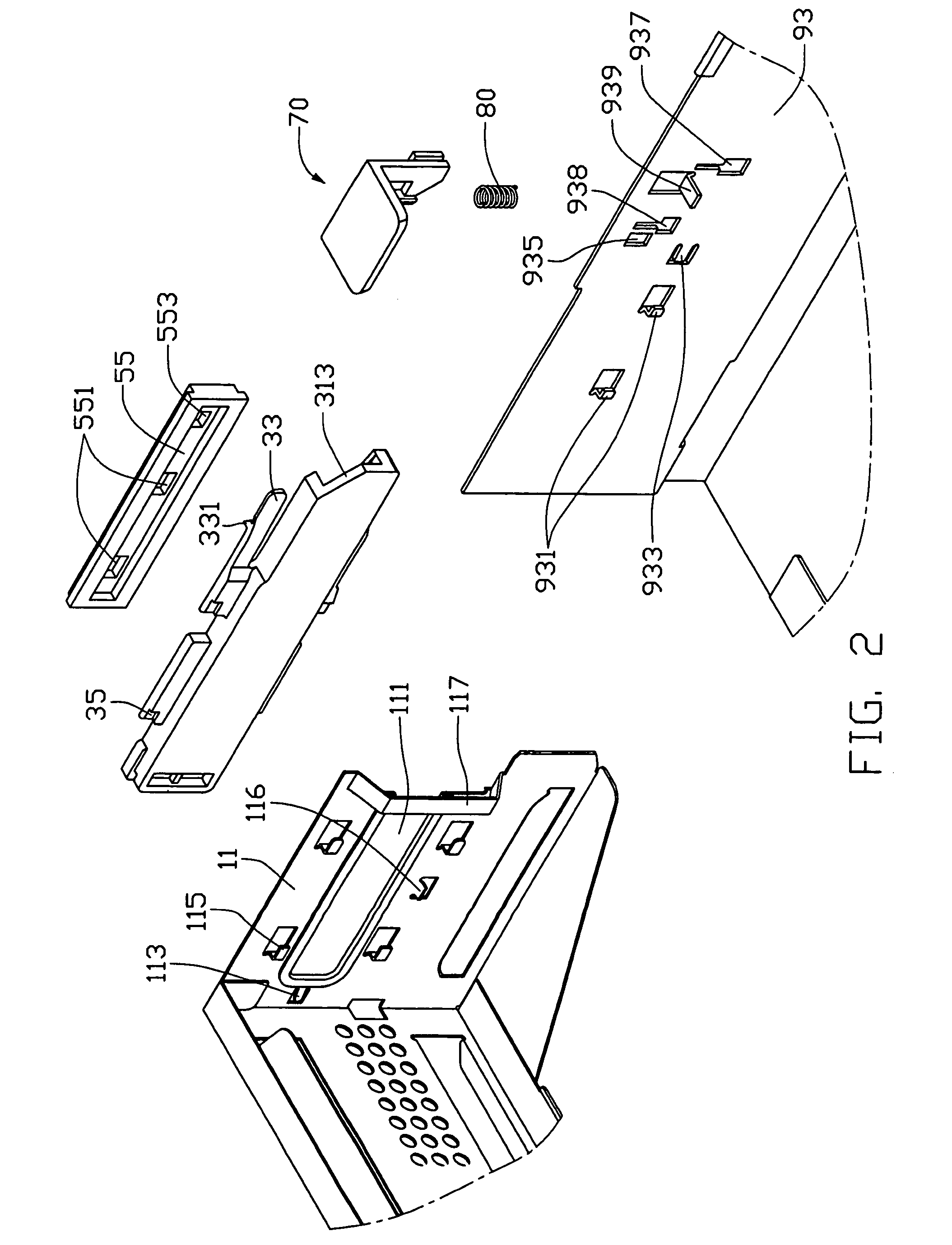
[0015]Referring to FIGS. 1 and 2, a mounting assembly of an enclosure of an electronic device like a computer in accordance with a preferred embodiment of the present invention includes a front panel 10, a pair of locking members 30, a pair of sliding members 50, a pair of pressing members 70 and a chassis 90.

[0016]The front panel 10 has a frontwall 13 and two opposite sidewalls 11. The frontwall 13 is bent inwardly and vertically to form flanges 131 at top and bottom edges thereof, and the lower flange 131 defines a plurality of cutouts 133. An elongated opening 111 is defined in the sidewall 11 of the front panel 10. A locking tab 113 is formed on the sidewall 11 of the front panel 10 adjacent to the opening 111. A plurality of L-shaped hooks 115 is formed on the inner side of sidewall 11 at an upper edge and a lower edge of the opening 111. A protruding tab 116 is formed on the inner side of the sidewall 11 under the opening 111. A connecting bridge 117 rides over the opening 111...


PUM


Abstract

A mounting assembly of a computer enclosure includes a chassis (90), a front panel (10) slidably mounted to the chassis (90), a pair of locking members (30) attached to the front panel (10), a pair of sliding members (50) fixedly attached to the chassis (90) and a pair of pressing members (70) movably mounted to the chassis (90) for unlocking the locking members (30). Each sliding member (50) has a sliding portion (53). Each locking member (30) defines a sliding groove (31) therein. The sliding portion (53) of the sliding member (50) is engaged in the sliding groove (31) for securing the front panel (10) on the chassis (90).

Description

BACKGROUND OF THE INVENTION[0001]1. Field of the Invention[0002]The present invention relates to a mounting assembly of a computer enclosure, and more particularly to a mounting assembly of a computer enclosure for attaching or detaching a front panel conveniently.[0003]2. Background of the Invention[0004]With the advancement of science and technology, computers are widely used in every walk of life. More and more computer users hope to detach a computer enclosure conveniently for checking malfunction of hardware and repairing interior components of a computer. However, nowadays, with the tide of miniature computer enclosure, computer users are of inconvenience in operation in incommodious computer enclosure. In addition, an expanded function of the computer enclosure is also limited. Therefore, it is required that a front panel should be demounted conveniently from a chassis. A typical mounting assembly is that a front panel is directly riveted to a chassis or a front panel is inte...

Claims


Application Information

Patent Timeline
Patent Type & Authority Patents(United States)
IPC IPC(8): H05K5/00
CPCG06F1/181Y10S292/11Y10T292/1028
Inventor CHEN, YUN-LUNGJIANG, FA-MINGSU, GANG
Owner HONG FU JIN PRECISION IND (SHENZHEN) CO LTD
Why Eureka
Try Eureka