Network element for implementing scheduled high-power PTP and low-power PTMP transmissions

a network element and low-power technology, applied in data switching networks, multiplex communication, high-level techniques, etc., can solve the problems of not being able to use fixed wireline access, difficult to deploy copper or optical cables, and high cost, and achieve the effect of minimizing interference between backhaul ptp and access ptmp networks

Inactive Publication Date: 2008-12-16
RPX CLEARINGHOUSE
View PDF10 Cites 65 Cited by
  • Summary
  • Abstract
  • Description
  • Claims
  • Application Information

AI Technical Summary

Benefits of technology

[0012]The present invention provides a network element for implementing scheduled high-power Point To Point (PTP) and low-power Point To MultiPoint (PTMP) transmissions. According to an embodiment of the invention, a network element is provided that has both high-power Point To Point (PTP) and low-power Point To MultiPoint (PTMP) antennas that may be used to transmit data in scheduled bursts on a given frequency channel in a wireless network. The network element is provided with an air interface that is configured to transmit data on both PTP links and PTMP links to enable both high-power backhaul and low-power access bursts to be scheduled on the network. The use of an air interface for both types of communications allows the PTP and PTMP communications to be scheduled relative to each other in a unified manner so that interference between the backhaul PTP and access PTMP networks may be minimized even though the PTP and PTMP communications to take place on the same RF frequency channel and according to the same underlying wireless technology.

Problems solved by technology

For example, deploying a copper or optical cable is relatively difficult and, hence expensive, as compared to the relative ease with which a wireless link may be established interconnect the base station with the core network.
Additionally, when the base station is mobile, base station it is not possible to use fixed wireline access to provide a backhaul connection between the base station and the fixed wireline network.

Method used


Image

  • Network element for implementing scheduled high-power PTP and low-power PTMP transmissions
  • Network element for implementing scheduled high-power PTP and low-power PTMP transmissions
  • Network element for implementing scheduled high-power PTP and low-power PTMP transmissions

Examples


Embodiment Construction

[0022]The following detailed description sets forth numerous specific details to provide a thorough understanding of the invention. However, those skilled in the art will appreciate that the invention may be practiced without these specific details. In other instances, well-known methods, procedures, components, protocols, algorithms, and circuits have not been described in detail so as not to obscure the invention.

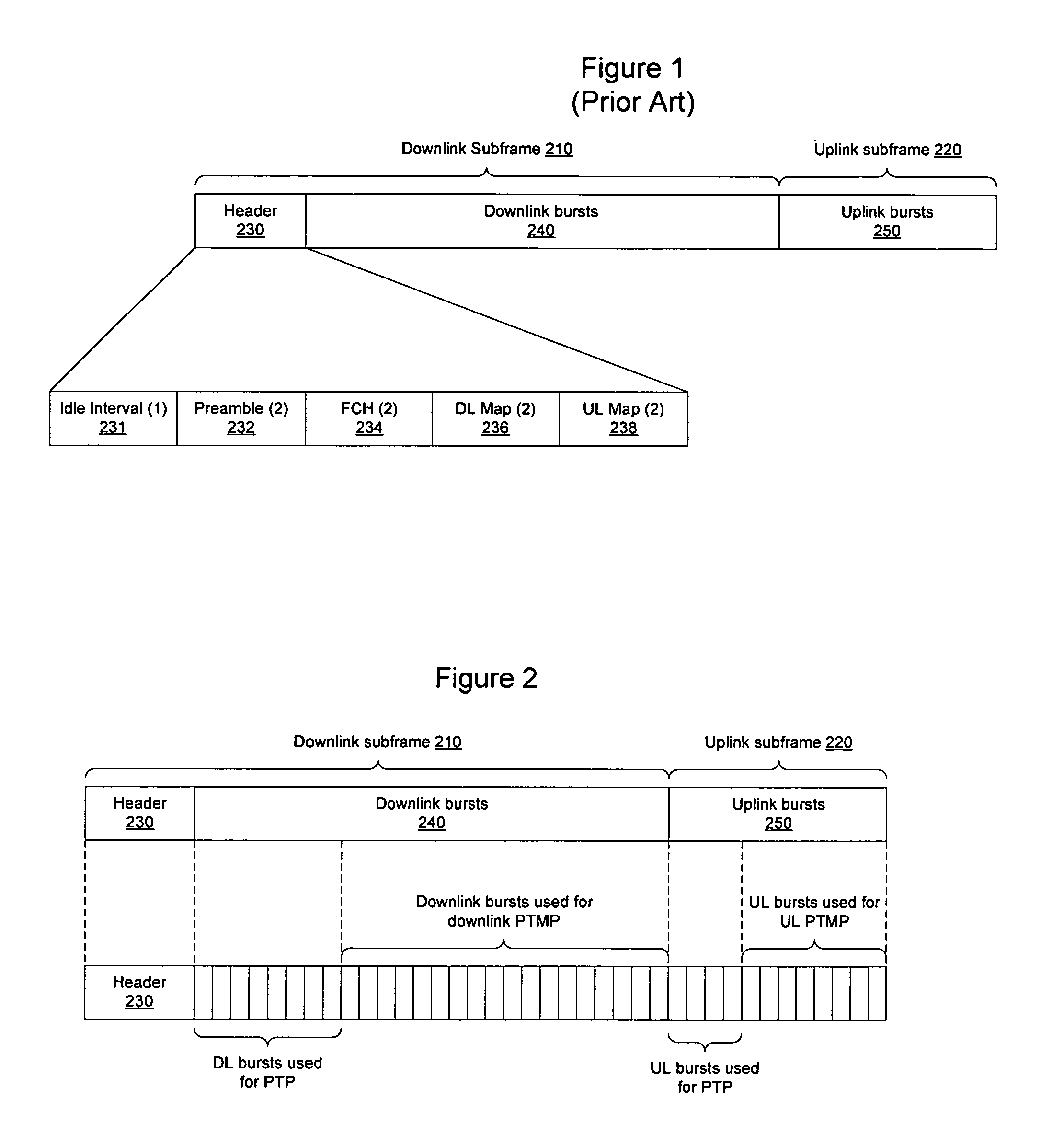
[0023]FIG. 2 is a representative diagram of a frame format formed according to the 802.16 standard that may be used to transmit PTP and PTMP communications via a network element according to an embodiment of the invention. As shown in FIG. 2, the frame includes a downlink subframe 210 and an uplink subframe 220, containing timeslots to carry downlink bursts 240 and timeslots to carry uplink bursts 250. The downlink bursts may be scheduled to include PTP bursts in the downlink direction, PTMP bursts in the downlink direction, PTMP bursts in the uplink direction, and PTP bu...


PUM


Abstract

A network element is configured to implement scheduled high-power Point-To-Point (PTP) and low-power Point-To-MultiPoint (TMP) transmissions. The high-power PTP and low-power PTMP transmissions may be scheduled as bursts on an 802.16 network to occur in both the downlink subframe and uplink subframe on a given frequency channel in the wireless network. The use of an air interface for both types of communications allows the PTP and PTMP communications to be scheduled relative to each other in a unified manner to increase quality of service and minimize interference between the backhaul PTP and access PTMP networks, even though the PTP and PTMP communications take place on the same channel using the same underlying wireless technology. Buffers may be used to store data received in a PTP downlink burst prior to transmission in a PTMP downlink burst, and may be used to store data received in an uplink PTMP burst prior to transmission in an uplink PTP burst.

Description

BACKGROUND OF THE INVENTION[0001]1. Field of the Invention[0002]The invention relates to wireless network elements and, more particularly, to a network element for implementing scheduled high-power Point To Point (PTP) and low-power Point To MultiPoint (PTMP) transmissions.[0003]2. Description of the Related Art[0004]Wireless data communication networks may include base stations, relay stations, subscriber stations, and other network devices, interconnected and configured to handle data as it passes through the network. These devices will be referred to herein as “network elements.” In a wireless network, these network elements are interconnected by transmitting wireless signals in a portion of the electromagnetic spectrum.[0005]When signals are transmitted wirelessly, the distance at which an RF signal may be received is often directly related to the amount of power used to transmit the signal and the directionality of the antenna. Accordingly, the amount of power that may be used ...

Claims


Application Information

Patent Timeline
Patent Type & Authority Patents(United States)
IPC IPC(8): H04Q7/20H04W72/08H04W84/04H04W92/12
CPCH04W72/08H04W84/047H04W92/12Y02D30/70H04W72/54
Inventor HANDFORTH, MARTIN RIDGWAYNANNRA, ANOOPSTANKUS, JOHNMARCANTI, LARRYVEZZA, BRIAN
Owner RPX CLEARINGHOUSE
Why Eureka
Try Eureka