Battery cover latching assembly for portable electronic device

a technology for electronic devices and battery covers, applied in electrical equipment, substation equipment, cell components, etc., can solve the problems of difficult replacement of batteries in the mobile phone housing, easy damage to the battery cover, and relative great effort required to disassemble the battery cover

Inactive Publication Date: 2010-01-12
SHENZHEN FUTAIHONG PRECISION IND CO LTD +1
View PDF11 Cites 43 Cited by
  • Summary
  • Abstract
  • Description
  • Claims
  • Application Information

AI Technical Summary

Benefits of technology

[0006]A clasp structure or latch structure is used with a typical battery cover to engage with a housing of a portable electronic device. For example, the Alcatel OT310 mobile phone has a latch for the battery cover. The latch includes a pair of hooks at one end of the battery cover and a locking pin protruding from the other end of the battery cover. Accordingly, a pair of grooves are defined in an end portion of a backside of a housing of the mobile phone, and a locking hole is defined in the other end portion of the backside of the housing. In assembly, the hooks are inserted into the grooves in the backside of the housing. Then, the battery cover is pressed downwardly to the housing until the locking pin on the battery cover is inserted into the locking hole in the backside of the housing. The battery cover is thus assembled to the housing of the mobile phone. The battery cover is simple in structure, and the engagement between the battery cover and the housing of the mobile phone is firm. However, during disassembly, a relative great effort is needed to disassemble the battery cover, since a substantial force is exerted thereon. The battery cover can easily be damaged during such disassembly. As a result, it is difficult for a user to replace a battery in the housing of the mobile phone.

Problems solved by technology

The batteries have to be replaced by opening the battery covers when, for example, the batteries are damaged or dead (i.e. no longer rechargeable).
However, during disassembly, a relative great effort is needed to disassemble the battery cover, since a substantial force is exerted thereon.
The battery cover can easily be damaged during such disassembly.
As a result, it is difficult for a user to replace a battery in the housing of the mobile phone.

Method used


Image

  • Battery cover latching assembly for portable electronic device
  • Battery cover latching assembly for portable electronic device
  • Battery cover latching assembly for portable electronic device

Examples


Embodiment Construction

[0015]The present battery cover latching assembly is suitable for portable electronic devices, such as mobile phones, PDAs, and so on.

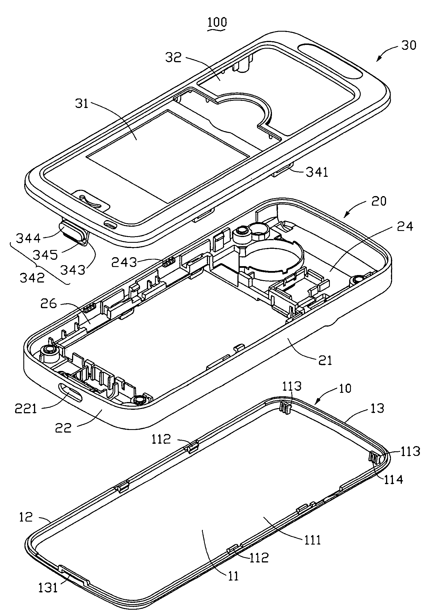
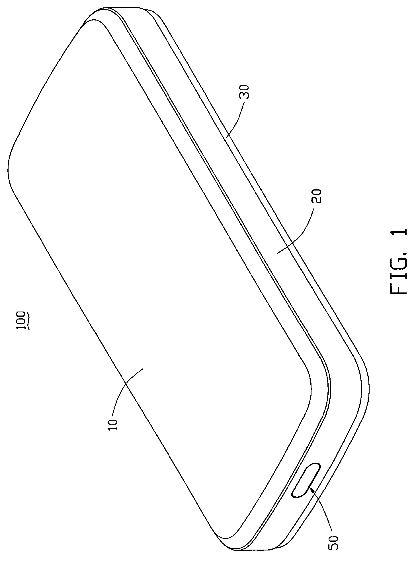
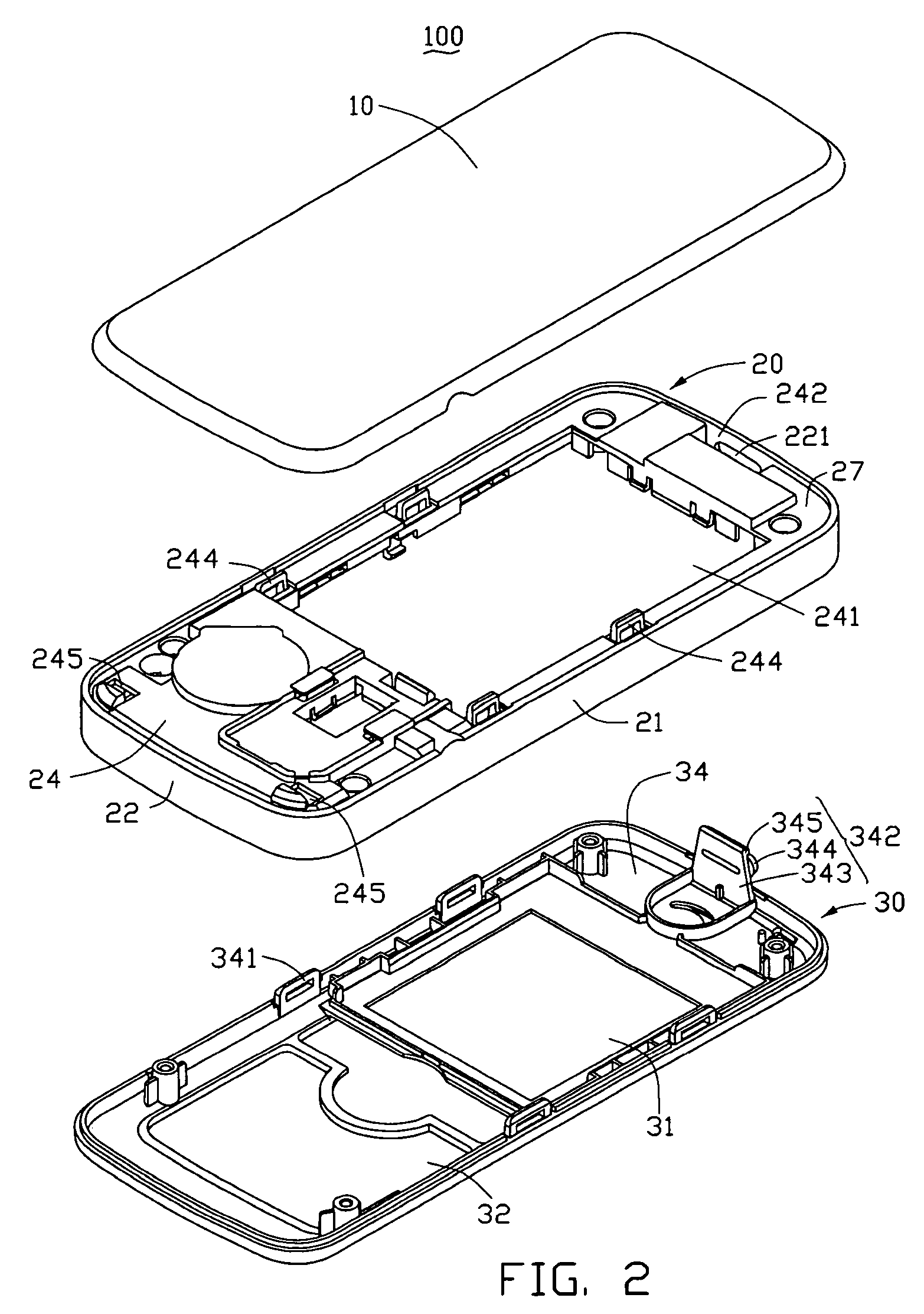
[0016]Referring now to the drawings in detail, FIG. 1 shows a battery cover latching assembly 50 incorporated in a mobile phone / portable electronic device 100. The mobile phone 100 is taken here as an exemplary application, for the purposes of describing details of the battery cover latching assembly 50 of the preferred embodiment. The mobile phone 100 includes a battery cover 10, a housing 20 and a front cover 30, all of which are connected via the battery cover latching assembly 50. Also referring to FIG. 2 and FIG. 3, the battery cover latching assembly 50 includes a locking portion 131, a button hole 221, a through hole 242, and a latch 342. The locking portion 131 is defined in the battery cover 10. The button hole 221 and the through hole 242 are defined in the housing 20. The latch 342 is formed on the front cover 30. The battery cover latching...


PUM


Abstract

A battery cover latching assembly (50) is for a portable electronic device (100) including a housing (20), a first cover (10) configured for attaching to a first side of the housing, and a second cover (30) configured for attaching to a second side of the housing. The battery cover latching assembly includes a locking portion (131) and a latch (342). The locking portion is formed on the first cover. The latch is formed on the second cover. The latch includes a body (343) and a button portion (344) extending from the body. The body is engageable with the locking portion so as to lock the first cover and second cover with each other. The button portion is configured so as to be retained by the housing, and is operable to deform the body of the latch so as to unlock the first cover and the second cover.

Description

CROSS-REFERENCE TO RELATED APPLICATION[0001]The present application is related to the commonly-assigned U.S. patent application Ser. No. 11 / 377,790, entitled “BATTERY COVER LATCHING ASSEMBLY FOR PORTABLE ELECTRONIC DEVICE,” filed on Mar. 16, 2006 with the same inventors, the contents of which are hereby incorporated by reference thereto.BACKGROUND[0002]1. Technical Field[0003]The present invention generally relates to cover latching assemblies and, more particularly, to a battery cover latching assembly for use in a portable electronic device.[0004]2. Discussion of the Related Art[0005]Batteries are widely used in portable electronic devices, such as personal digital assistants (PDAs), mobile phones, and so on. Typical batteries are attachably received in the electronic device, and battery covers are designed to connect with housings of the electronic devices to package the batteries. The batteries have to be replaced by opening the battery covers when, for example, the batteries ar...

Claims


Application Information

Patent Timeline
Patent Type & Authority Patents(United States)
IPC IPC(8): H04M1/00
CPCH01M2/1066Y02E60/10H01M50/209H01M50/00
Inventor ZUO, ZHOU-QUANCHEN, CHIA-HUA
Owner SHENZHEN FUTAIHONG PRECISION IND CO LTD
Why Eureka
Try Eureka