Sliding track coupling structure for sliding doors

a sliding door and coupling structure technology, applied in the field of sliding tracks, can solve the problems of inconvenient use and inflexible adaptation of fixed tracks

Inactive Publication Date: 2010-06-29
GOOD CREDIT CORP
View PDF16 Cites 38 Cited by
  • Summary
  • Abstract
  • Description
  • Claims
  • Application Information

AI Technical Summary

Problems solved by technology

Because of installation sites vary widely the conventional fixed track cannot be flexibly adapted, thus is not convenient in use.

Method used


Image

  • Sliding track coupling structure for sliding doors
  • Sliding track coupling structure for sliding doors
  • Sliding track coupling structure for sliding doors

Examples


Embodiment Construction

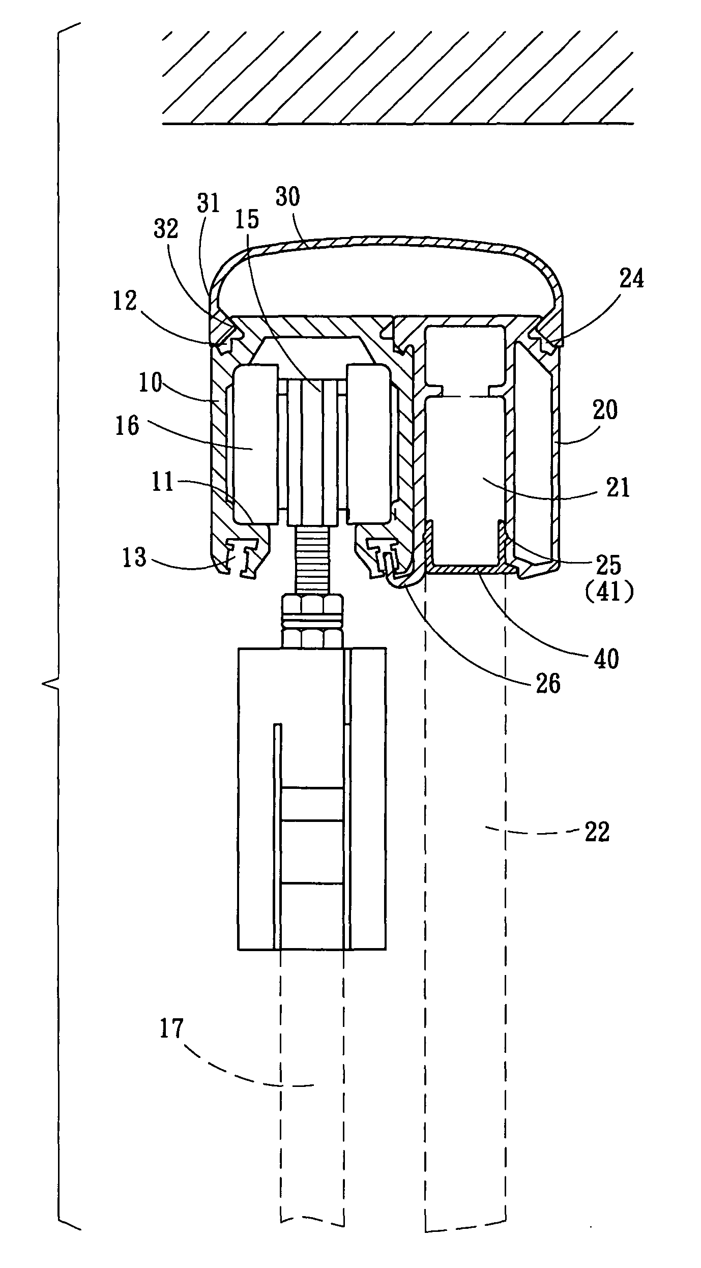
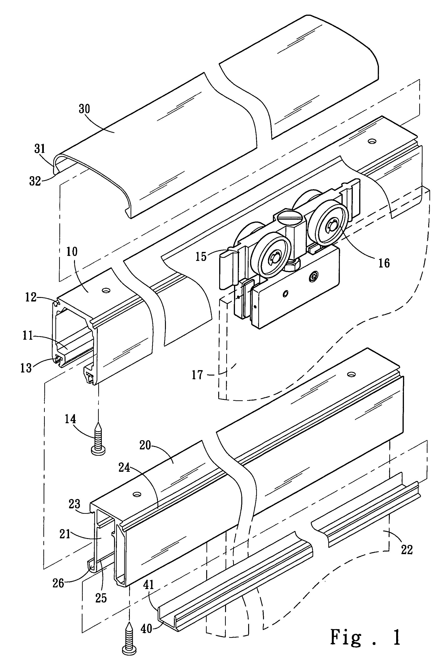
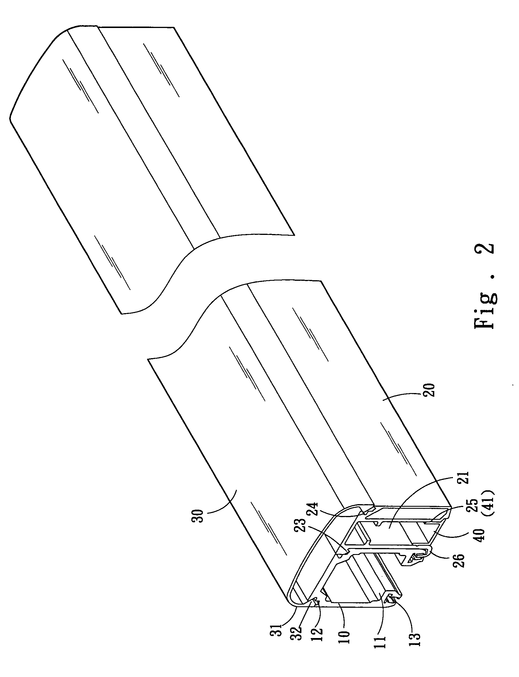
[0011]Please refer to FIGS. 1 and 2, the sliding track coupling structure for sliding doors of the invention includes:

[0012]a sliding door track 10 which has an inverted U-shape cross section with an opening facing downwards. The sliding door track 10 has a left wall and a right wall on two sides that have respectively an inner wall with a pair of guiding tracks 11 formed thereon. The sliding door track 10 further has a first wedge troughs 12 on an upper left corner and an upper right corner, and a pair of second wedge troughs 13 on the left side and right side of the bottom thereof. The top of the sliding door track 10 is fastened to a ceiling through a fastening element 14 (such as a screw) directing upwards;

[0013]a hanging track 15 which has a plurality of rollers 16 located on the left side and right side in a transverse manner. It also is fastened to a sliding door 17 on a lower side;

[0014]a glass fixed panel track 20 which has a top portion fastened to a ceiling through anothe...


PUM


Abstract

A sliding track for sliding doors includes a sliding door track and a glass fixed panel track which have an inverted U-shape cross section with an opening facing downward. The sliding door track has a left and a right inner wall that have a pair of guiding tracks formed thereon to allow a plurality pairs of rollers which are hinged on a hanging track which is fastened to a sliding door on a lower side to roll thereon in a straddle manner. The sliding door track further has a pair of first wedge troughs on the upper left and upper right corners, and a pair of second wedge troughs on a lower side. The first and second wedge troughs are coupled with the glass fixed panel track. The sliding door track and the glass fixed panel track may also be coupled with an ornamental plate on the top. The glass fixed panel track may further be coupled with a sealing plate on the bottom.

Description

FIELD OF THE INVENTION[0001]The present invention relates to a sliding track above a sliding door and particularly to a sliding track that can be individually installed and flexibly removed according to different installation sites.BACKGROUND OF THE INVENTION[0002]The general sliding doors (may be glass doors driven electrically) can provide partition function and do not take much space during opening and closing, thus are widely used. For instance they are commonly used on shops or bathrooms to separate an inner room and an outer room. Some sliding doors are fixedly fastened to the ceiling. Some other sliding doors have the top portion spaced from the ceiling at a selected distance to provide desired air ventilation and light projection effect. Some sliding doors are mounted onto one side of a glass fixed panel to facilitate opening and closing of the sliding doors. There are also sliding doors installed on display windows of shops. The display windows have a glass fixed panel on o...

Claims


Application Information

Patent Timeline
Patent Type & Authority Patents(United States)
IPC IPC(8): E05D15/06
CPCE05D15/0652E05Y2800/16E05Y2900/132E05Y2800/672Y10T16/379E05Y2201/684E05Y2800/21Y10T16/376E05Y2201/614E05Y2201/11
Inventor LIAO, SHOU-HSING
Owner GOOD CREDIT CORP
Why Eureka
Try Eureka