Projector

a projector and projector technology, applied in the field of projectors, can solve the problems of increasing the relative size of the interval must be secured, and the aberration so as to achieve the effect of bright projection image, reducing the diameter of the collecting lens, and reducing the absorption of ligh

Inactive Publication Date: 2010-12-21
OLYMPUS CORP
View PDF10 Cites 1 Cited by
  • Summary
  • Abstract
  • Description
  • Claims
  • Application Information

AI Technical Summary

Benefits of technology

[0013]An object of the present invention, which was made in view of the circumstances described above, is to provide a projector in which an outgoing aperture and a point light source are disposed sufficiently near to each other, aberration is reduced, the diameter of a collecting lens is reduced, and a bright projected image can be obtained while reducing the overall size of the projector.
[0014]Further, an object of the present invention, which was made in view of the circumstances described above, is to provide a projector which previously prevents occurrence of such a disadvantage that the looking / listening environment in a looking / listening space is deteriorated by the noise and hot air generated by a light source apparatus, can be installed even in a small looking / listening space, and can realize a comfortable looking / listening environment.

Problems solved by technology

However, there is a disadvantage in that since a relatively large mirror must be disposed actually, a relatively large interval must be secured between the illuminating light diaphragm and the aperture diaphragm or between the image of the lamp light source and the aperture diaphragm.
That is, when the interval is increased, the amount of decentration of the optical axis of the illuminating light which is incident on and outgoes from the collecting lens increases, which is disadvantageous in that aberration is increased.
Further, there is also a drawback in that the diameter of collecting lenses disposed at intervals along an optical axis must be increased to retrieve the illuminating light which is incident on and outgoes from the collecting lens as much as possible.
Further, when it is intended to obtain a point light source having high brightness using a lamp light source, there is also a disadvantage in that since the lamp light source is increased in size as well as accessories such as a cooling fan and the like for suppressing heat generated by the lamp light source are also increased in size, a projector is increased in size in its entirety.
Accordingly, there is a drawback in that the sound generated by the cooling fan when it is driven in rotation is noisy.
Accordingly, in a small and closed looking / listening space such as a vehicle compartment, a problem arises in that the S / N ratio of sound of images is greatly increased by the noise of the cooling fan, and further the temperature of the compartment is increased by the hot air discharged from the fan.
Further, since the projector includes components occupying a relatively large space, for example, the lamp such as the xenon lamp and the like of the light source apparatus, the cooling fan, and the optical system including lenses and the like, there is also a problem in that the projector is increased in size and thus it is difficult to dispose it in the small looking / listening space.

Method used


Image

  • Projector
  • Projector
  • Projector

Examples


first embodiment

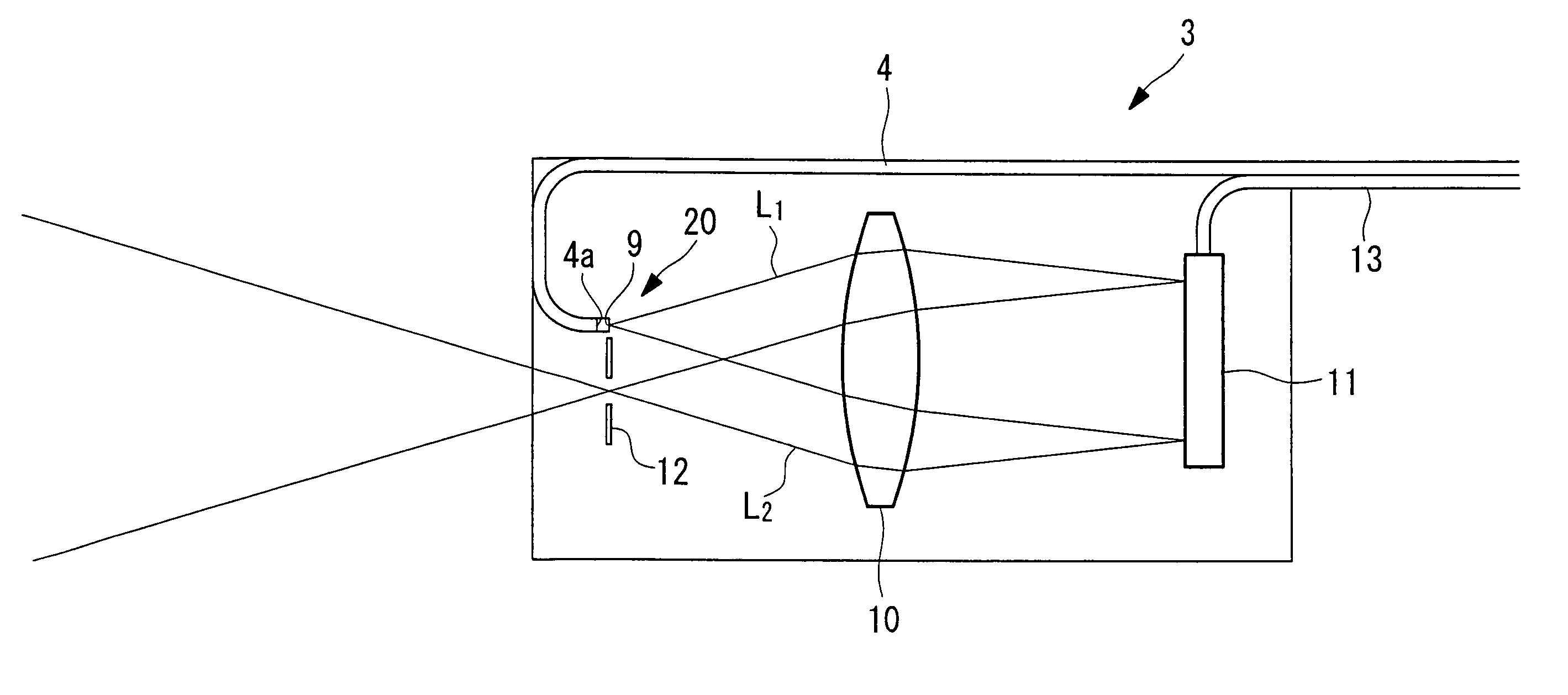
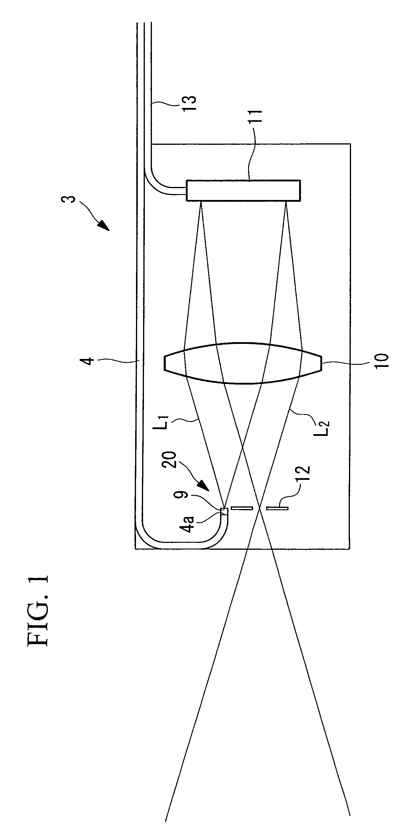
[0043]A projector according to a first embodiment of the present invention will be described below referring to FIGS. 1 and 2.

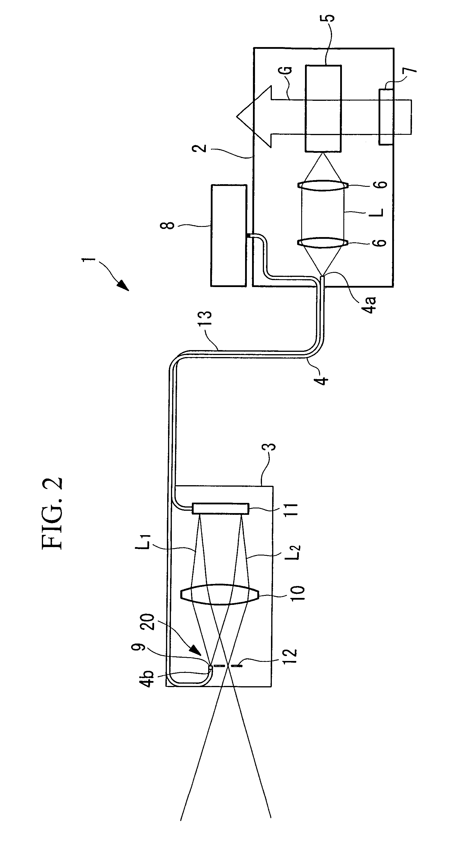
[0044]As shown in FIG. 2, the projector 1 according to the embodiment includes a light source apparatus 2, a projector head 3, and a flexible optical fiber 4 for connecting the light source apparatus 2 to the projector head 3.

[0045]The light source apparatus 2 includes a laser light source 5 and coupling lenses 6 for collecting the laser light (exciting light) L emitted from the laser light source 5. Since the laser light source 5 generates heat in operation, the light source apparatus 2 is provided with a cooling fan 7 for carrying out forcible cooling by, for example, an air flow G. Further, a controller 8 is disposed to the light source apparatus 2 to control a digital micromirror device (Trademark) 11 of the projector head 3 to be described later.

[0046]The optical fiber 4 is, for example, a multimode fiber having an edge face 4a disposed to a light collec...

second embodiment

[0063]A projector according to a second embodiment of the present invention will be described below referring to FIG. 4.

[0064]Hereinafter, the same or similar components as those of the first embodiment will be described using the same reference numeral.

[0065]As shown in FIG. 4, the projector 101 according to the embodiment includes a light source apparatus 102, a projector head 103, and a flexible optical fiber 4 for connecting the light source apparatus 102 to the projector head 103.

[0066]The light source apparatus 102 includes a xenon lamp 105 and coupling lenses 6 for collecting the white light Lw emitted from the xenon lamp 105. Since the xenon lamp 105 generates heat in operation, the light source apparatus 102 is provided with a cooling fan 7 for carrying out forcible cooling by, for example, an air flow G. Further, a controller 108 is disposed to the light source apparatus 102 side to control a display device 110 of the projector head 103 to be described later.

[0067]The opti...


PUM


Abstract

There is provided a projector having a point light source disposed to an edge of an optical fiber for transmitting exciting light and including a fluorescent illuminant for emitting fluorescence by being exited by the exiting light, a light collecting optical system for collecting the fluorescence emitted from the point light source, a reflective display device for reflecting the fluorescence collected by the light collecting optical system and overlapping the fluorescence with an image signal, an outgoing aperture for stopping down the fluorescence overlapped with the image signal by the reflective display device, wherein the outgoing aperture and the point light source are disposed side by side in the vicinity of the front focusing surface of the light collecting optical system. With this arrangement, a bright projected image can be obtained while disposing the outgoing aperture and the point light source sufficiently near to each other, reducing aberration, and reducing the diameter of a collecting lens so that the overall size of the projector can be reduced.

Description

BACKGROUND OF THE INVENTION[0001]1. Field of the Invention[0002]This application is based on Japanese Patent Applications Nos. 2005-377867, and 2005-377868, the content of which is incorporated herein by reference.[0003]2. Description of Related Art[0004]The present invention relates to a projector.[0005]Conventionally, there is known a projector arranged such that a reflective display device such as a digital micromirror device (Trademark)(DMD (Trademark)) and a collecting lens are disposed side by side in an optical axis direction, and an aperture diaphragm and an illuminating light diaphragm are disposed at the front focusing position of the collecting lens in a direction orthogonal to the optical axis (refer to, for example, Japanese Unexamined Patent Application Publication No. 8-251520). Further, there is also disclosed a projector which has no illuminating light diaphragm and has a point light source arranged by focusing an image of a lamp light source on a focusing surface o...

Claims


Application Information

Patent Timeline
Patent Type & Authority Patents(United States)
IPC IPC(8): G03B21/00
CPCG03B21/00G03B21/26G03B21/005
Inventor TAKAHASHI, SUSUMU
Owner OLYMPUS CORP
Why Eureka
Try Eureka