Torque device for a sensor guide wire

a technology of torque device and sensor guide wire, which is applied in the field of torque device for sensor guide wire, can solve the problems of particularly prone damage of sensor guide wire, and achieve the effect of facilitating the compression of chuck segments

a technology of torque device and sensor guide wire, which is applied in the field of torque device for sensor guide wire, can solve the problems of particularly prone damage of sensor guide wire, and achieve the effect of facilitating the compression of chuck segments

US8038628B2Active Publication Date: 2011-10-18ST JUDE MEDICAL COORDINATION CENT

Image

  • Torque device for a sensor guide wire
  • Torque device for a sensor guide wire
  • Torque device for a sensor guide wire

Examples


Embodiment Construction

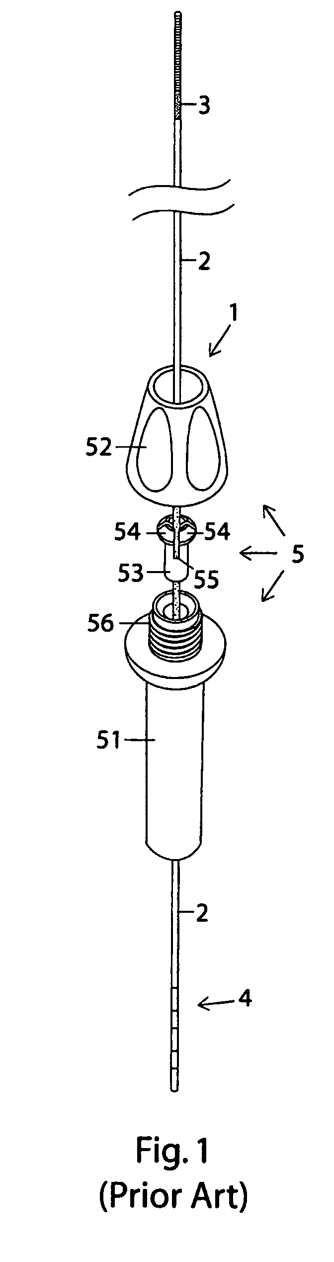
[0018]FIG. 1 illustrates schematically the essential parts of a sensor and guide wire assembly 1 comprising a sensor guide wire 2, a sensor element 3 provided in or at a distal portion of the sensor guide wire 2, a male connector 4 arranged at the proximal end of the sensor guide wire 2, and a torque device 5 disposed somewhere along the length of the sensor guide wire 2. With exception of the torque device 5, the sensor and guide wire assembly 1 can be regarded as a generic sensor and guide wire assembly, which also can be used in combination with the novel torque device in accordance with the present invention and described below.

[0019]To make it easier to appreciate the special advantages of the novel torque device according to the invention, the features of the known torque device 5 will be described in some detail in conjunction with FIG. 1. The torque device 5, which has a lumen adapted for reception of a sensor guide wire, comprises three parts: a grip portion 51, a cap 52, a...


PUM


Abstract

The invention relates to a torque device for a sensor guide wire having a sensor provided at a distal portion and a male connector provided at the proximal end, which torque device comprises a grip body and a cap adapted to be joined to the grip body, and a number of chuck segments provided on the cap or the grip body, wherein the torque device is a one-way device defining an insertion direction for the sensor guide wire and wherein the chuck segments have free ends which are directed in the insertion direction.

Description

FIELD OF THE INVENTION[0001]The invention relates generally to sensors mounted on guide wires for intravascular measurements of physiological variables in a living body, and in particular to the design of a torque device which is attached to the guide wire and by which the sensor is maneuvered to a specific measurement site within the living body.BACKGROUND OF THE INVENTION[0002]Sensor and guide wire assemblies in which a sensor, adapted for measurements of physiological variables in a living body, such as blood pressure and temperature, is mounted at a distal portion of a guide wire are known.[0003]For example, the U.S. Pat. No. Re. 35,648 (which is assigned to the present assignee and incorporated herein by reference for the devices and techniques disclosed therein) discloses a sensor and guide wire assembly comprising a sensor element, an electronic unit, signal transmitting cables connecting the sensor element to the electronic unit, a flexible tube having the signal cables and ...

Claims


Application Information

Patent Timeline
18 Oct 2011
Publication
US8038628B2
IPC
A61M25/00
CPC
A61B5/0215; A61B5/061
Inventors
VON MALMBORG, PAR; GUSTAFSSON, PAR