Connector device

a technology of connecting devices and connectors, applied in the direction of coupling contact members, coupling device connections, connection contact member materials, etc., can solve the problems of difficult to ensure data transmission reliability, and achieve the effect of reducing or eliminating the influence of stubs and improving crosstalk characteristics

Inactive Publication Date: 2011-11-01
FUJITSU COMPONENENT LTD
View PDF15 Cites 40 Cited by
  • Summary
  • Abstract
  • Description
  • Claims
  • Application Information

AI Technical Summary

Benefits of technology

[0021]The present invention has been devised in consideration of the above-mentioned situation, and an object of the present invention is to provide a connector device in which a crosstalk characteristic is improved, and transmission characteristics are improved.
[0023]According to the present invention, for the jack ground contacts and the plug ground contacts, because stubs are reduced in their lengths, or, more preferably, no stubs are included, an influence of the stubs is reduced or eliminated, and a crosstalk characteristic is improved.

Problems solved by technology

Therefore, in a case where a signal is transmitted at such a high transmission rate as tens of Gbps in near future, it may become difficult to guarantee reliability in data transmission.

Method used


Image

  • Connector device
  • Connector device
  • Connector device

Examples


embodiment 1

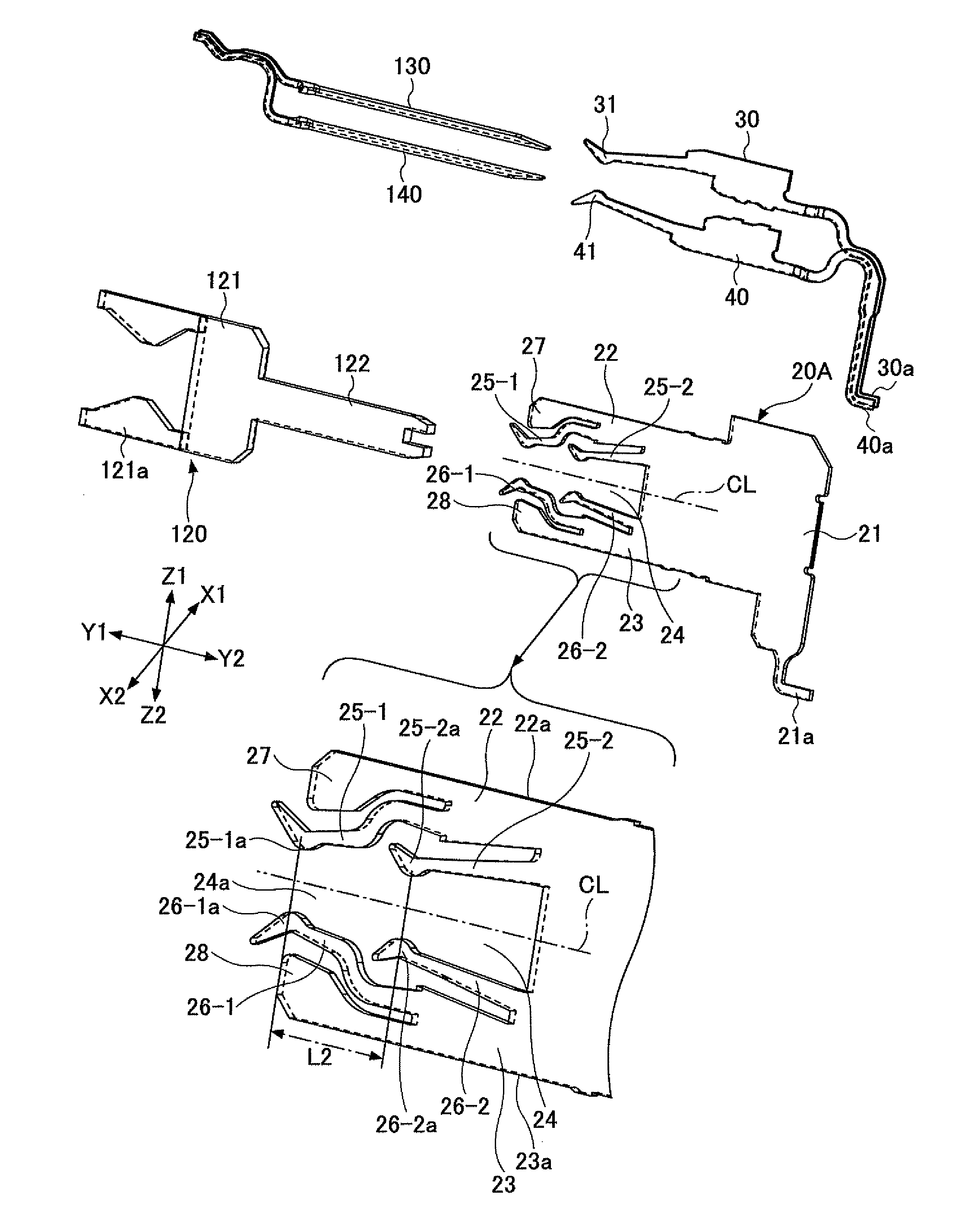
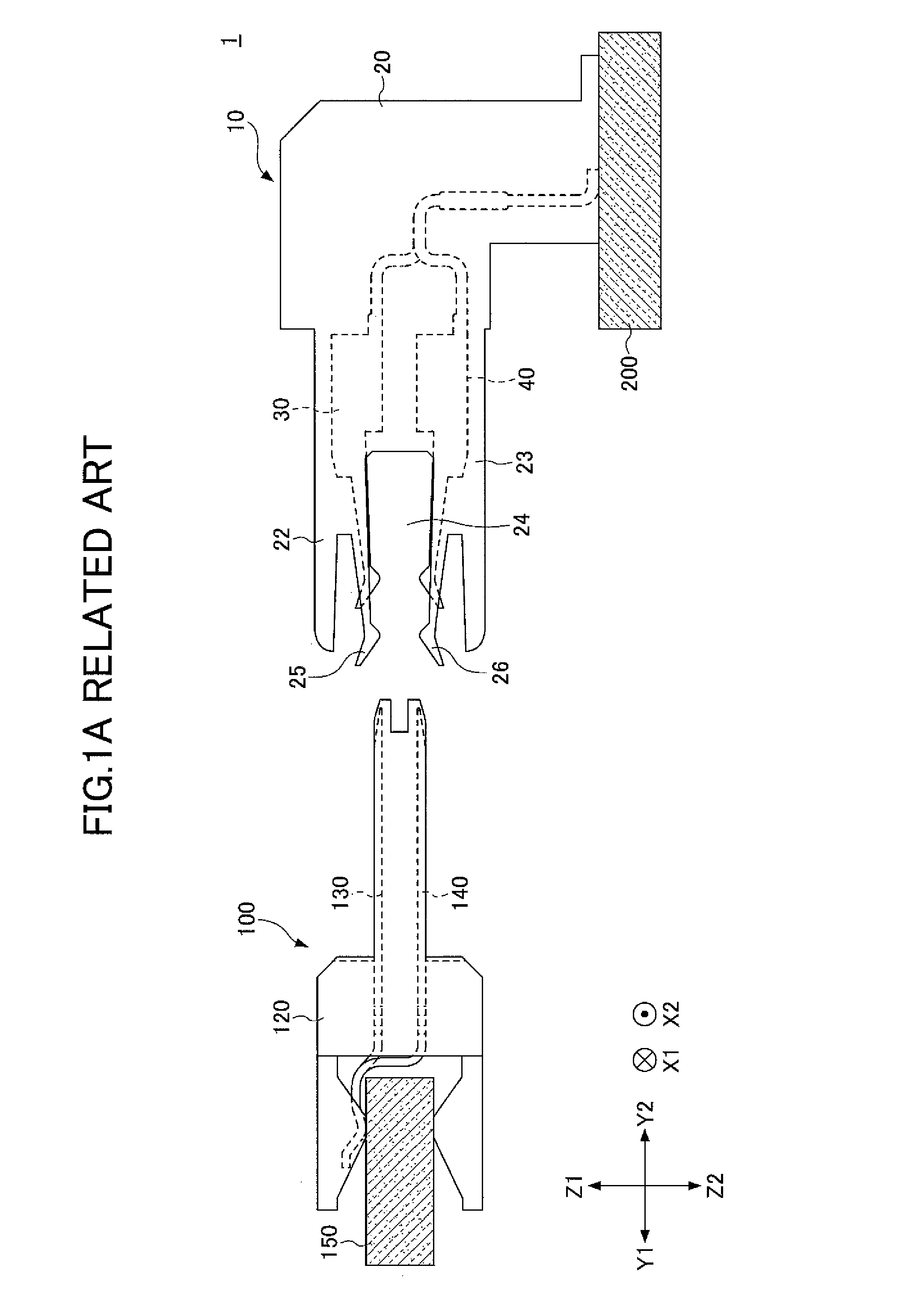
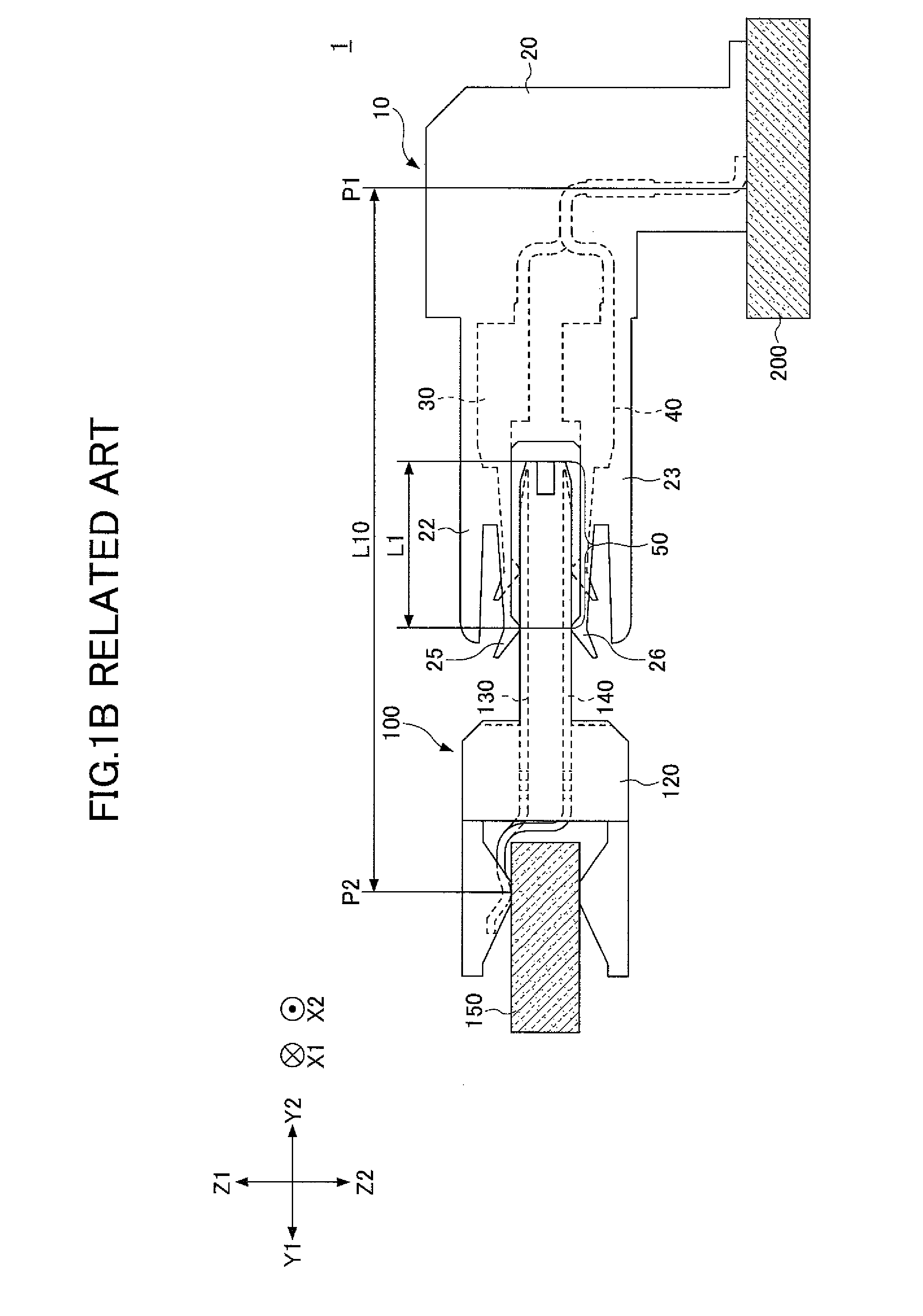
[0037]FIGS. 2A and 2B respectively depict a plug connector 100, acting as a male part having parts that stick out and fit into corresponding recesses of a female part, and a jack connector 10A acting as a female part having the recesses of a balanced transmission connector device 1A in an embodiment 1 of the present invention. FIG. 3 depicts a state in which the plug connector 100 is connected to the jack connector 10A.

[0038]Hereinafter, X1-X2 directions denote row directions of an arrangement of contacts of plug and jack connectors (width directions of the plug and jack connectors), Z1-Z2 directions denote column directions of the arrangement of contacts (height directions of the plug and jack connectors), and Y1-Y2 directions denote length directions of the plug and jack connectors (depth directions of the plug and jack connectors, or directions in which the plug and jack connectors are inserted / removed therebetween).

[Configuration of Plug Connector 100]

[0039]The plug connector 10...

embodiment 2

[0087]FIGS. 12, 13A and 13B depict a balanced transmission connector device 1B in an embodiment 2 of the present invention, in such a manner that respective contacts face each other. The balanced transmission connector device 1B includes a jack connector 10B and a plug connector 100B.

[0088]The jack connector 10B and the plug connector 100B are identical to the jack connector 10 and the plug connector 100 depicted in FIGS. 1A, 1B, respectively, except for the following points. The same reference numerals are given to the same / corresponding parts / components, and duplicate description will be omitted appropriately.

[0089]The jack connector 10B is configured such that the above-mentioned gaskets 80, 81 are provided to the jack connector 10 depicted in FIGS. 1A, 1B, and includes first and second signal contacts 30, 40 and ground contacts 20.

[0090]The plug connector 100B includes first and second signal contacts 130, 140 and ground contacts 120B, in which the ground contacts 120B are modif...


PUM


Abstract

A jack connector includes pairs of jack signal contacts and jack ground contacts arranged alternately, and a plug connector includes pairs of plug signal contacts and plug ground contacts arranged alternately. Respective contacts of each pair of jack signal contacts come into contact with respective contacts of each pair of plug signal contacts, and each jack ground contact comes into contact with each plug ground contact. In a first contact structure, each jack ground contact comes into contact with each plug ground contact at a first position, and in a second contact structure each jack ground contact comes into contact with each plug ground contact at a second position apart from the first position along an extending direction of the plug ground contact.

Description

CROSS-REFERENCE TO RELATED APPLICATIONS[0001]This application is based upon and claims the benefit of priority of the prior Japanese Patent Application No. 2009-016442, filed on Jan. 28, 2009, the entire contents of which are incorporated herein by reference.BACKGROUND OF THE INVENTION[0002]1. Field of the Invention[0003]The present invention relates to a connector device, and, in particular, to a connector apparatus including a jack connector for a balanced transmission system (differential transmission system) and a plug connector for a balanced transmission system (differential transmission system).[0004]2. Description of the Related Art[0005]As systems for data transmission, there are an ordinary transmission system (single-end system) and a balanced transmission system (differential transmission system). In the single-end system, a single electric wire is used for each data. In the balanced transmission system, a pair of electric wires are used for each item of data, a positive...

Claims


Application Information

Patent Timeline
Patent Type & Authority Patents(United States)
IPC IPC(8): H01R24/00H01R13/646H01R13/6471H01R13/658H01R13/6585
CPCH01R13/6315H01R23/688H01R13/6471H01R13/65807H01R13/506H01R13/6584
Inventor YAMAKAMI, TOHRUOKUYAMA, TAKESHIKUMAMOTO, TADASHI
Owner FUJITSU COMPONENENT LTD
Why Eureka
Try Eureka