Bi-stable bifurcated stent petal geometry

a stent and bifurcation technology, applied in the field of bifurcation bifurcated stent petal geometry, can solve the problems of many prior art stents not being wholly satisfactory for us

Inactive Publication Date: 2012-10-02
BOSTON SCI SCIMED INC
View PDF502 Cites 89 Cited by
  • Summary
  • Abstract
  • Description
  • Claims
  • Application Information

AI Technical Summary

Problems solved by technology

Many prior art stents however are not wholly satisfactory for use where the site of desired application of the stent is juxtaposed or extends across a bifurcation in an artery or vein such, for example, as the bifurcation in the mammalian aortic artery into the common iliac arteries.

Method used


Image

  • Bi-stable bifurcated stent petal geometry
  • Bi-stable bifurcated stent petal geometry
  • Bi-stable bifurcated stent petal geometry

Examples


Embodiment Construction

[0048]While this invention may be embodied in many different forms, there are described in detail herein specific embodiments of the invention. This description is an exemplification of the principles of the invention and is not intended to limit the invention to the particular embodiments illustrated.

[0049]For the purposes of this disclosure, like reference numerals in the figures shall refer to like features unless otherwise indicated.

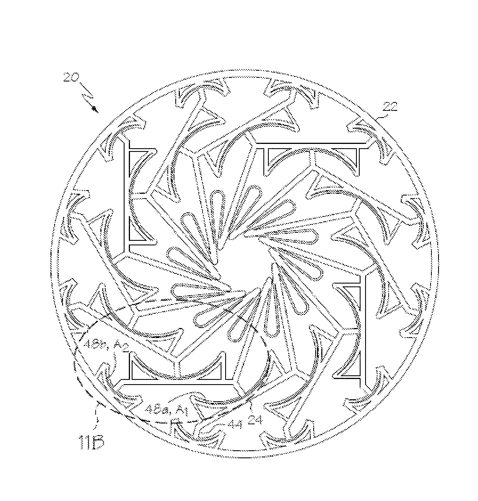
[0050]As used herein the term ‘stent’ refers to an expandable prosthesis for implantation into a body lumen or vessel and includes devices such as stents, grafts, stent-grafts, vena cava filters, expandable frameworks, etc.

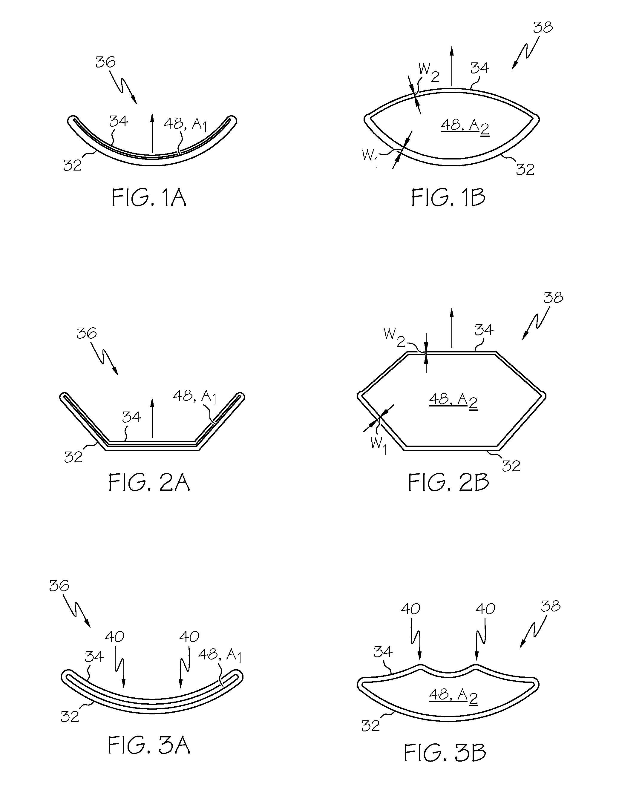
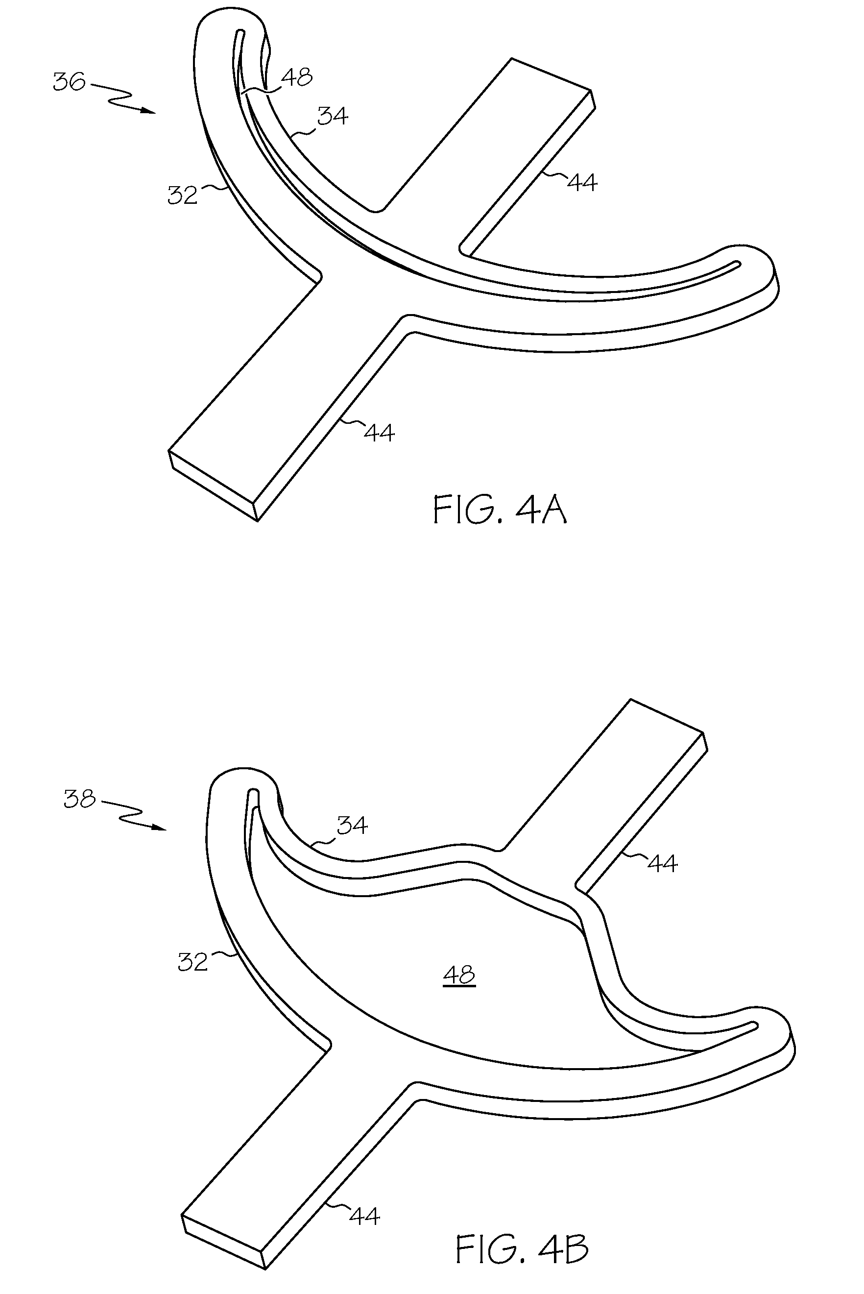
[0051]As used herein, the term ‘bi-stable cell’ refers to a cell that has two or more discrete stable configurations, geometries and / or states 36,38. Thus, bi-stable cells includes cells that are multi-stable, i.e. cells with more than two discrete stable configurations.

[0052]Referring now to the drawings which are for the purposes...


PUM


Abstract

A stent has a substantially cylindrical tubular body with at least one expandable side branch that has a plurality of members. The plurality of members includes at least one first member having a first width and at least one second member having a second width, where the first width is greater than the second width. Each of the at least one first members and each of the at least one second members define a cell that has at least two stable cell geometries.

Description

CROSS-REFERENCE TO RELATED APPLICATIONS[0001]Not ApplicableSTATEMENT REGARDING FEDERALLY SPONSORED RESEARCH[0002]Not ApplicableBACKGROUND OF THE INVENTION[0003]A stent is a medical device introduced to a body lumen and is well known in the art. Typically, a stent is implanted in a blood vessel at the site of a stenosis or aneurysm endoluminally, i.e. by so-called “minimally invasive techniques” in which the stent in a radially reduced configuration, optionally restrained in a radially compressed configuration by a sheath and / or catheter, is delivered by a stent delivery system or “introducer” to the site where it is required. The introducer may enter the body from an access location outside the body, such as through the patient's skin, or by a “cut down” technique in which the entry blood vessel is exposed by minor surgical means.[0004]Stents, grafts, stent-grafts, vena cava filters, expandable frameworks, and similar implantable medical devices are radially expandable endoprosthese...

Claims


Application Information

Patent Timeline
Patent Type & Authority Patents(United States)
IPC IPC(8): A61F2/82
CPCA61F2/856A61F2/915A61F2250/0036
Inventor CHALEKIAN, AARONZHANG, NAMEYER, MICHAEL P.ROSSMAN, TIM
Owner BOSTON SCI SCIMED INC
Why Eureka
Try Eureka