Suture manipulating and cutting implement

a technology of manipulating implements and cutting tools, applied in the field of manipulating implements, can solve the problems of difficult access to tight joints, limited instrument size and space available for manipulating, and inability to tie knots in situ, etc., and achieve the effect of convenient execution

Active Publication Date: 2012-10-09
T MEDICAL DEVICES AGRI COOP
View PDF21 Cites 39 Cited by
  • Summary
  • Abstract
  • Description
  • Claims
  • Application Information

AI Technical Summary

Benefits of technology

[0018]It will thus be seen that an implement constructed in accordance with the foregoing features enables the surgeon to introduce the suture into the open slot by a sidewise movement of the elongated shaft with respect to the knotted suture, or vice-versa. Such a movement can be much more conveniently executed by the surgeon, especially under the conditions prevailing in the operating room, than threading the suture through a bore in the implement as required by the prior devices. In addition, an implement using such an open slot for receiving the suture enables the implement to accommodate a much larger range of suture diameters, materials and types, than one using a bore for receiving the suture, and cuts the suture to a precise length above the knot.

Problems solved by technology

The size of this opening limits the size of the instruments used and the space available to manipulate them.
In particular, access to tight joints is difficult.
Tying a knot in situ is, however, barely possible.
The length of the suture end remaining after cutting is important: If it is too long, it may cause irritation; if it is too short, the knot may fail to hold.
Insofar as we are aware, all instruments available on the market fail to include one or more of the above desirable features.
One drawback of the above device is that it is difficult to thread the suture through the bore, especially under the conditions prevailing in the operating room.
Also, the practicable dimensions of the bore restrict the range of suture types for which the device can be used.
That implement, however, also includes a bore through which the suture is to be threaded, and therefore would have the same drawbacks as described above with respect to the device commercially available since 1999.

Method used


Image

  • Suture manipulating and cutting implement
  • Suture manipulating and cutting implement
  • Suture manipulating and cutting implement

Examples


Embodiment Construction
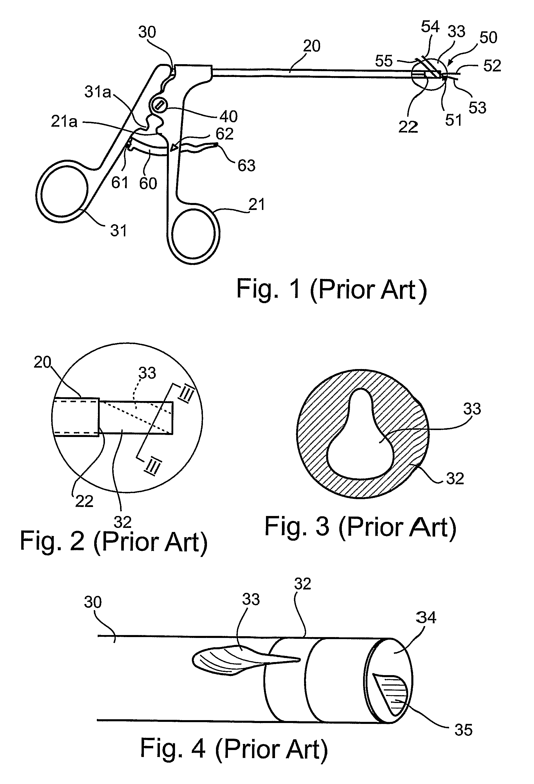
. 1-4

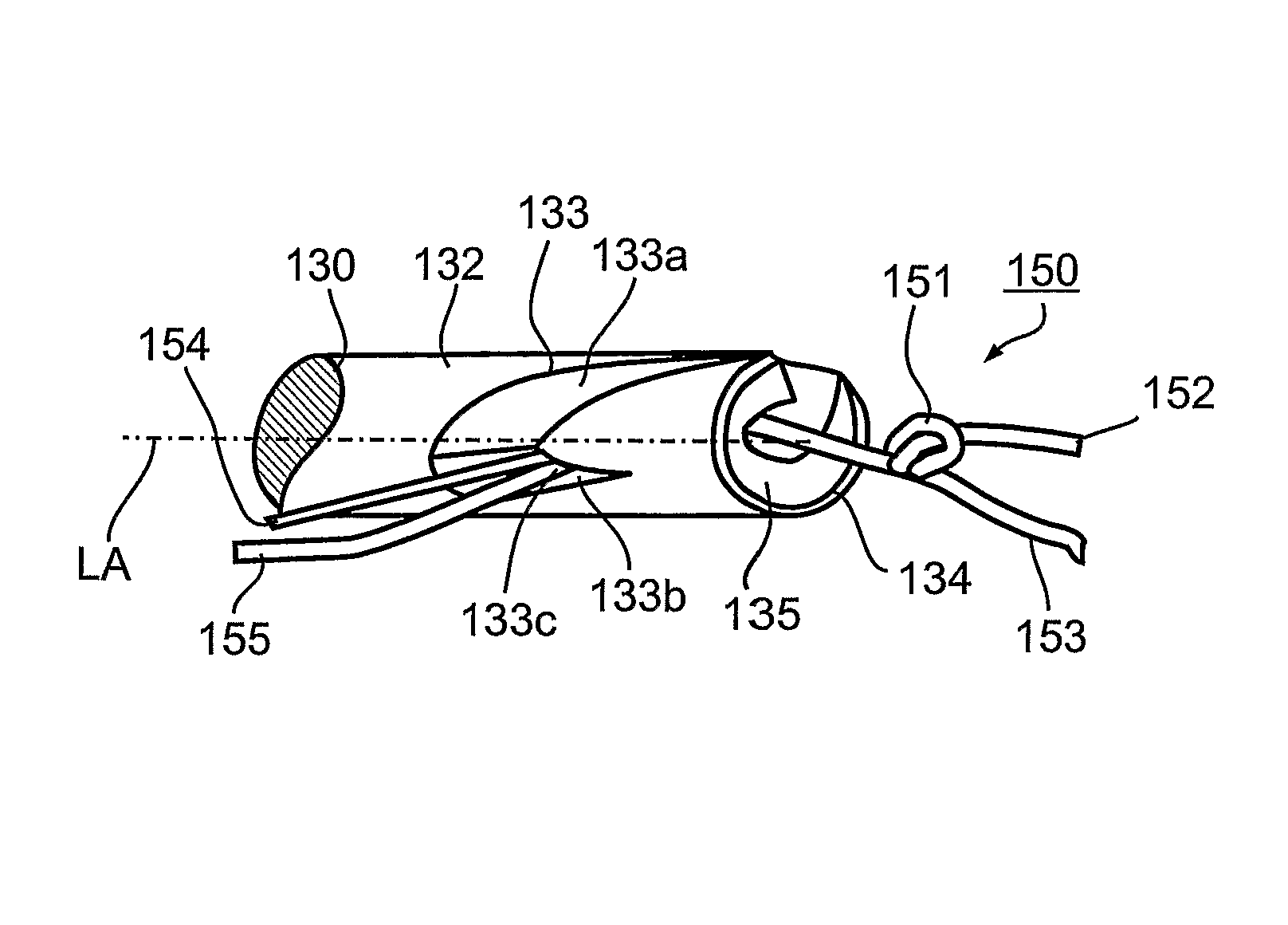
[0029]FIG. 1 illustrates a suture manipulating and cutting implement constructed in accordance with the prior art as briefly described above. The illustrated implement includes a tubular cutter member 20 having a proximal end formed with a handle 21, and an elongated shaft 30 moveable within cutter member 20 and also having a proximal end formed with a handle 31. The two handles 21, 31 are pivotally mounted to each other about a pin 40.

[0030]The distal end of tubular cutter member 20 is formed with an annular cutter edge 22 on its inner surface circumscribing the outer surface of the elongated shaft 30.

[0031]Elongated shaft 30 has a distal end 32 formed with an angled bore 33 for receiving the suture, schematically shown at 50 in FIG. 1. Bore 33 is sized to allow suture 50 to be threaded through it at angle to the axis of shaft 30. The cross-section of bore 33 is in the form of a droplet as shown particularly in FIGS. 3 and 4. The end face 34 of elongated shaft 30 is countersun...


PUM


Abstract

An implement for manipulating a knotted suture during a surgical procedure, includes an elongated shaft having a proximal end engageable by the user for manipulating the instrument, and a distal end engageable with the knotted suture to be manipulated. The distal end of the elongated shaft has an end face formed with a recess for receiving the knot of the suture. The distal end of the elongated shaft is formed with an open slot starting from a location spaced from the end face and leading to the recess in the end face, such as to enable the knotted suture to be introduced into the slot and the recess by effecting a sidewise movement. The implement further includes a tubular cutter member enclosing the elongated shaft and formed with an annular cutting edge engageable with a suture in the open slot of the shaft upon movement of the elongated shaft with respect to the tubular cutter member, or by vice-versa.

Description

RELATED APPLICATIONS[0001]This application is a National Phase Application of PCT Patent Application No. PCT / IL2005 / 000254 having International Filing Date of Mar. 3, 2005, which claims the benefit of U.S. Provisional Patent Application No. 60 / 549,553 filed on Mar. 4, 2004. The contents of the above Applications are all incorporated herein by reference.FIELD AND BACKGROUND OF THE INVENTION[0002]The present invention relates to a suture manipulating implement, and particularly to a surgical instrument for manipulating a knotted suture to properly locate the knot thereof with respect to the tissue being sutured, and then for removing excess suture from the knot.[0003]There is a growing demand to perform surgery, wherever possible, through small portals leading directly to the location operated on, thus minimizing damage to overlying and adjacent tissue. The technique is also known by the name endoscopy. Arthroscopy is the term used for the endoscopic approach applied to treat the vari...

Claims


Application Information

Patent Timeline
Patent Type & Authority Patents(United States)
IPC IPC(8): A61B17/04A61B17/00
CPCA61B17/0467A61B17/0469A61B17/0483A61B2017/00353A61B2017/0474
Inventor OREN, RANMOOR, DAN
Owner T MEDICAL DEVICES AGRI COOP
Why Eureka
Try Eureka