Two-for-one twisting or cabling spindle

a twisting spindle and cabling technology, applied in the direction of piercing arrangements, continuous wounding machines, textiles and paper, etc., can solve the problems of increasing energy requirements, reducing the service life of the twisting spindle, and reducing the service life of the revolving yarn balloon. , to achieve the effect of large spacing

Inactive Publication Date: 2012-11-13
ZHUOLANG INTELLIGENT MACHINERY CO LTD
View PDF14 Cites 0 Cited by
  • Summary
  • Abstract
  • Description
  • Claims
  • Application Information

AI Technical Summary

Benefits of technology

[0018]Relatively slim yarn balloons can be realised with a two-for-one twisting or cabling spindle apparatus, wherein the largest diameter of the rotatably mounted hollow spindle is at least 10% less than the diameter of a touching line of the pot base of the stationary protective pot with the yarn. These slim yarn balloons have the advantage that the ventilation losses occurring during operation at the two-for-one twisting or cabling spindle apparatus are clearly reduced, which leads to a noticeable reduction in the drive energy required during the operation of such two-for-one twisting or cabling spindle apparatus.
[0020]However, it may also be provided in an alternative embodiment that the spindle, apart from the storage disc, also has a yarn discharge plate fixed to the storage disc. A yarn discharge plate is generally fixed to the top of the storage disc and is an advantageous yarn guide means. In other words, a yarn discharge plate of this type ensures that the yarn is guided gently upward after leaving the storage disc and in the process forms a slim yarn balloon.
[0021]According to another advantageous embodiment, the yarn discharge plate has a curve-like edge region, which revolves with play during the twisting or cabling process in an annular recess, which is open at the bottom, of the pot base of the protective pot. The air swirls generally occurring in the edge region of a rotating yarn discharge plate can be minimised by a configuration of this type.
[0022]Another advantageous embodiment provides that the pot base of the stationary protective pot has, on its outside, along which the yarn slides during the twisting or cabling process, a yarn-friendly deflection radius. Owing to a yarn-friendly deflection radius of this type, the measurement of which is between 8 mm and 20 mm, it is ensured that the yarn sliding along the pot base during the twisting or cabling process is not too strongly loaded or even damaged.
[0024]By switching on an adapter of this type, the touching face of the yarn on the pot base can be minimised and, at the same time, the yarn balloon being produced during the twisting process can be made slimmer.

Problems solved by technology

However, as it is known that large yarn balloons lead to relatively large ventilation losses and therefore to an increased energy requirement of the two-for-one twisting spindle, various tests have already been carried out in the past, in particular in connection with less friction-sensitive yarn materials, such as, for example, cotton, to reduce or limit the diameter of the yarn balloons.
The drawback in these known two-for-one twisting spindle apparatus is, however, the relatively long physical contact of the revolving yarn balloon with the stationary balloon limiter.
As the stresses acting on the yarn owing to such stationary balloon limiters are relatively high, two-for-one twisting spindle apparatus of this type can only be used for relatively insensitive yarns.

Method used


Image

  • Two-for-one twisting or cabling spindle
  • Two-for-one twisting or cabling spindle
  • Two-for-one twisting or cabling spindle

Examples


Embodiment Construction

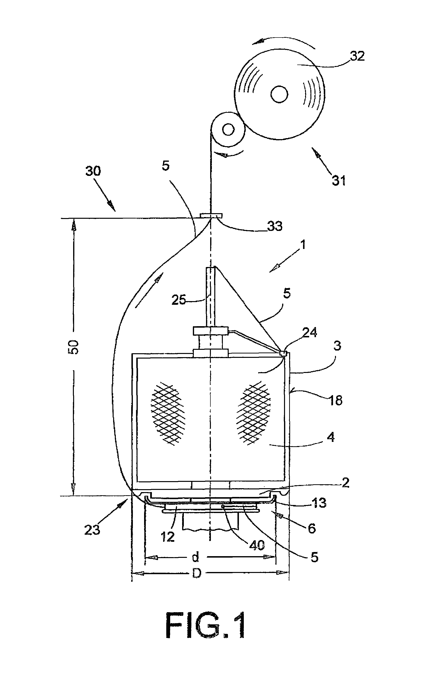
[0036]FIG. 1 schematically shows one representative workstation 30 of a multi-station two-for-one twisting or cabling machine (not shown in more detail). Workstations 30 of this type inter alia have a two-for-one twisting or cabling spindle apparatus 1, with a supply bobbin 4 mounted in a stationary protective pot 3 as well as a winding mechanism 31 for winding the twisted yarn 5 to form a take-up bobbin 32.

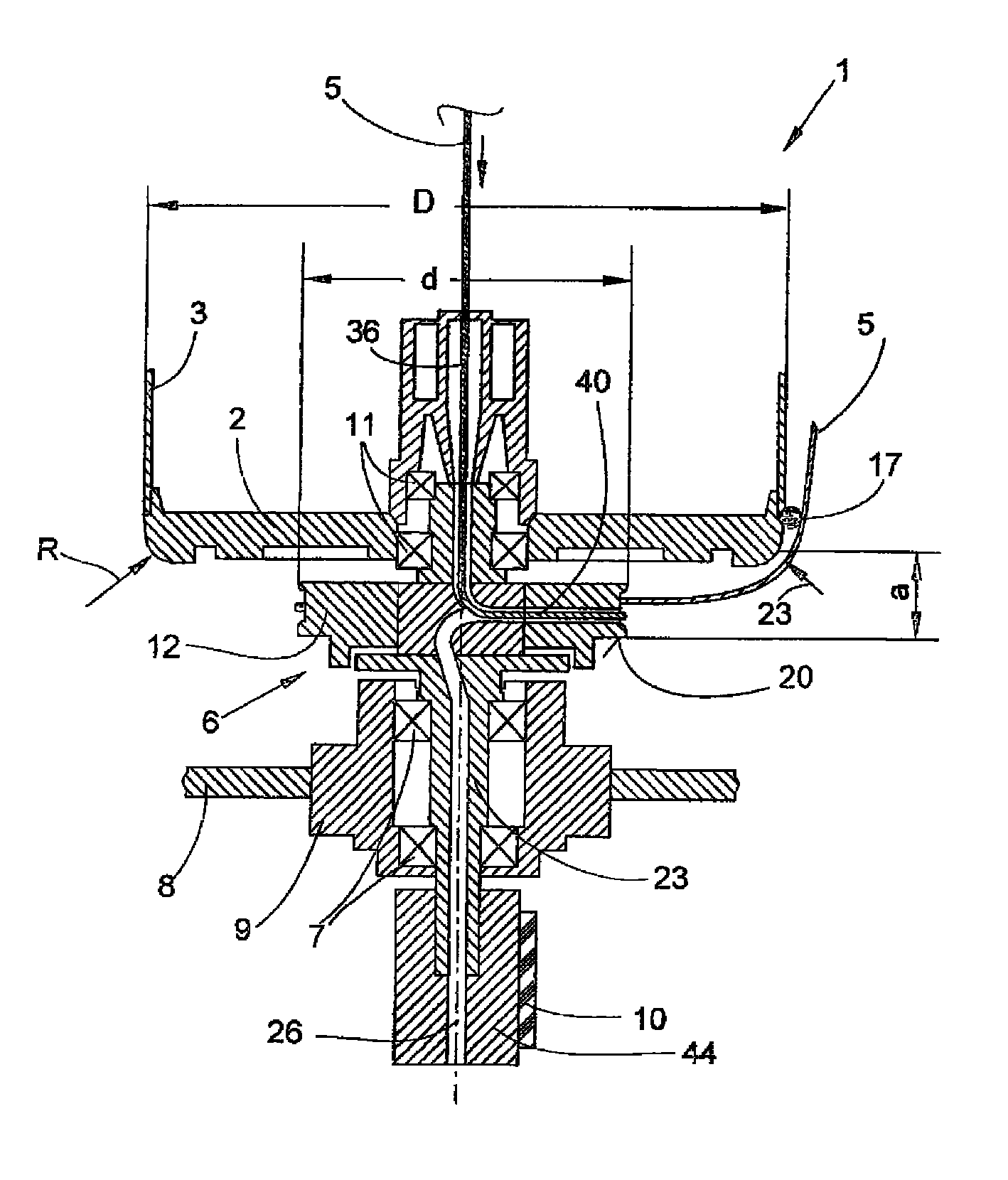
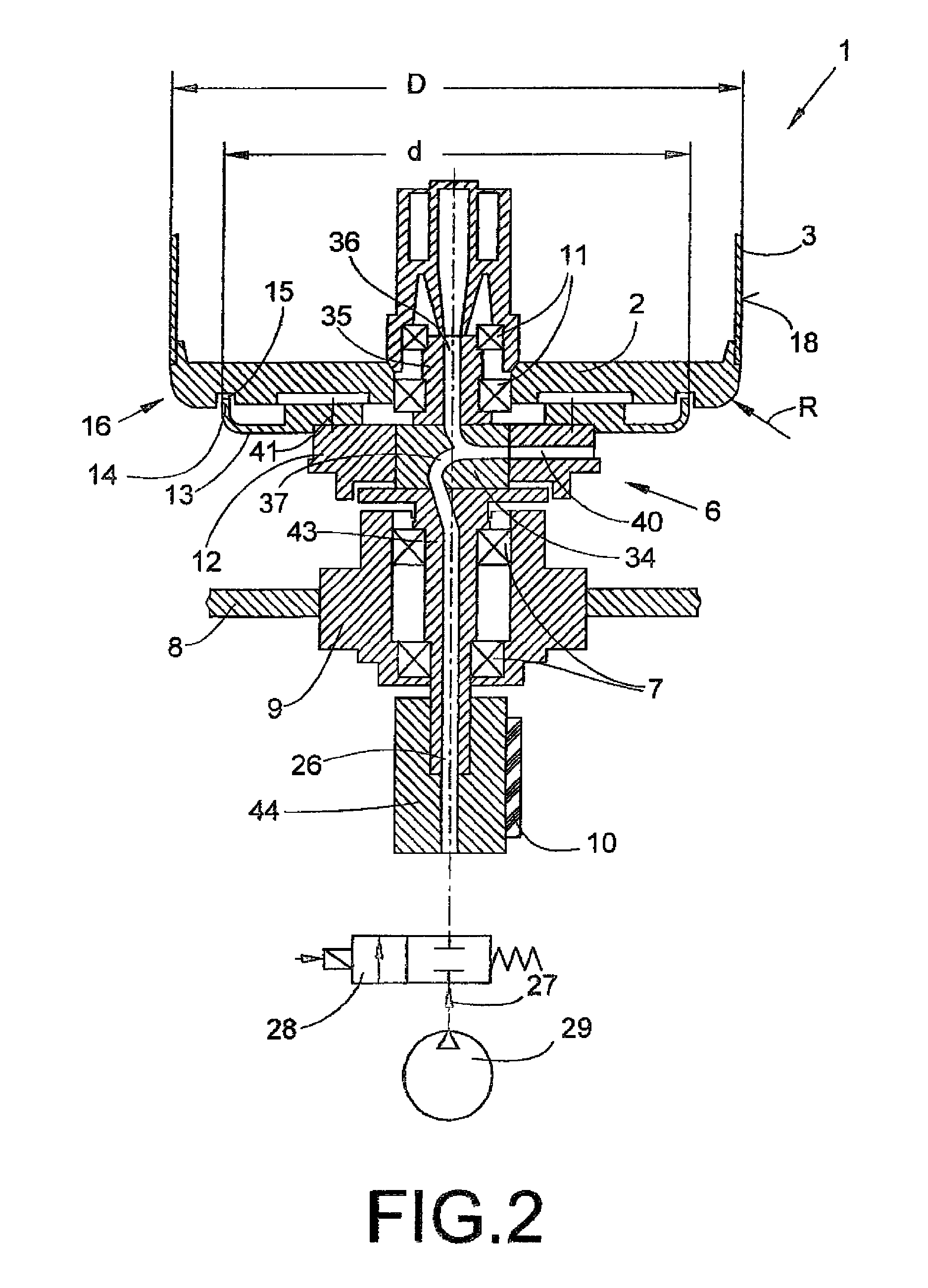
[0037]The stationary protective pot 3, which has a lateral pot surface 18 defining a relatively large diameter D, has a pot base 2. A rotatably mounted spindle 6 of the two-for-one twisting or cabling spindle apparatus 1 is arranged below the pot base 2.

[0038]In the embodiment shown in FIG. 1, the spindle 6, to rotate and guide the yarn 5 during the twisting or cabling process, is equipped with a storage disc 12 as well as with a yarn discharge plate 13, the diameter d of the yarn discharge plate 13, which in this case forms the largest diameter of the rotatably mounted spindle 6...


PUM

PropertyMeasurementUnit
deflection radiusaaaaaaaaaa
sizeaaaaaaaaaa

Abstract

A two-for-one twisting or cabling spindle apparatus (1) with a supply bobbin (4) mounted on a pot base (2) of a stationary protective pot (3) and a spindle (6) arranged below the protective pot (3) to guide a yarn (5) to be processed during a twisting or cabling process. The spindle (6) is rotatably mounted by a lower bearing device (7) in a bearing housing (9) fixed on a spindle rail (8) and an upper bearing device (11) mounted to the stationary protective pot (3). The largest diameter (d) of the rotatably mounted spindle (6) is at least 10% less than the diameter (D) of a touching line (23) of the pot base (2) of the stationary protective pot (3) with the yarn (5).

Description

CROSS-REFERENCE TO RELATED APPLICATIONS[0001]This application claims the benefit of German patent application DE 10 2010 013 795.2, filed Apr. 3, 2010, herein incorporated by reference.BACKGROUND OF THE INVENTION[0002]The invention relates to a two-for-one twisting or cabling spindle apparatus.[0003]Modern two-for-one twisting or cabling spindle apparatus generally have a stationary protective pot to receive a supply bobbin, a hollow bobbin axle to guide a yarn through the twisting spindle apparatus and a rotatably mounted, driveable spindle arranged below the supply bobbin. In other words, in two-for-one twisting or cabling spindle apparatus of this type, the yarn is drawn off upwardly from a stationary supply bobbin, inserted into the upper end of the hollow bobbin axle and deflected downwardly in the process. Within the bobbin axle, the yarn is guided via a yarn brake and then leaves the region of the bobbin axle via a radial opening, which is arranged in a component of the rotat...

Claims


Application Information

Patent Timeline
Patent Type & Authority Patents(United States)
IPC IPC(8): D01H7/86
CPCD01H1/106D01H7/868D01H15/007
Inventor BECKMANN, MARKUSHEINEN, GEORGLEUPERS, WOLFGANGPOHLMANN, GERDSCHNITZLER, JURGENSTRAHLEN, DIETERTETZLAFF, GEORG
Owner ZHUOLANG INTELLIGENT MACHINERY CO LTD
Why Eureka
Try Eureka