Display device

a display device and display screen technology, applied in harvesters, applications, instruments, etc., can solve the problem that the driver of the machine may not recognize a critical situation in time, and achieve the effect of simplifying monitoring and control tasks

Inactive Publication Date: 2013-02-05
CLAAS SELBSTFAHRENDE ERNTEMASCHINEN GMBH
View PDF28 Cites 16 Cited by
  • Summary
  • Abstract
  • Description
  • Claims
  • Application Information

AI Technical Summary

Benefits of technology

[0006]The object of the present invention is therefore to provide a display device with a display unit which simplifies the monitoring and control tasks performed by a driver of an agricultural machine.
[0008]According to the present invention, the values of the operating parameters are converted, e.g., to geometric figures (e.g., segments of circles), and they are brought into a spatial relationship with one another (the circle segments are combined to form a circular disk). As a result, it is possible to display a large number of operating parameters simultaneously by using simple diagrams (a circular disk). If the values of the operating parameters change, the individual geometric figures may also change. If the operating parameter increases, the corresponding geometric figure may be displayed larger in size, for example. An increase in the operating parameter may also be represented by the geometric figure moving away from the original position (the circle segment moves outwardly). As a result, the driver may be quickly alerted to a change in individual operating parameters from among a large number of operating parameters.
[0010]In a further embodiment according to the present invention, a display unit of the display device is provided, in the case of which, in the first operating state, the operating parameter lies below an upper threshold value or above a lower threshold value, and, in the second operating state, the operating parameter lies above an upper threshold value and / or below a lower threshold value. According to the present invention, a primary objective is to visually alert the driver to the fact that individual operating parameters are no longer within their working range, so that the driver may implement countermeasures.
[0014]According to a further embodiment of the present invention, a display unit is provided which is designed such that it includes a touchscreen function. As a result, it is possible to call up various layouts within one control menu, thereby making it possible to display different operating parameters, i.e., with different resolution.
[0019]Advantageously, it may also be provided that the first position includes a marking, the marking being designed to be visible to the driver. The markings make it possible, e.g., to visualize permissible working ranges of the corresponding operating parameters.
[0022]A subject of the present invention may be considered to be to provide a display unit, e.g., for agricultural working machines such as combine harvesters, forage harvesters, etc., the display unit being characterized by an extremely transparent structure in terms of the depiction of various operating parameters of the working machine, thereby ensuring that the driver of the working machine obtains a quick overview of critical operating parameters of the working machine and may easily change them; the display unit itself guides the operator through the setting menus that must be utilized to change the critical parameter.

Problems solved by technology

In addition to overloading the driver, another major disadvantage of this is that, under certain circumstances, the driver of the machine may not recognize a critical situation in time or at all.

Method used


Image

  • Display device
  • Display device
  • Display device

Examples


Embodiment Construction

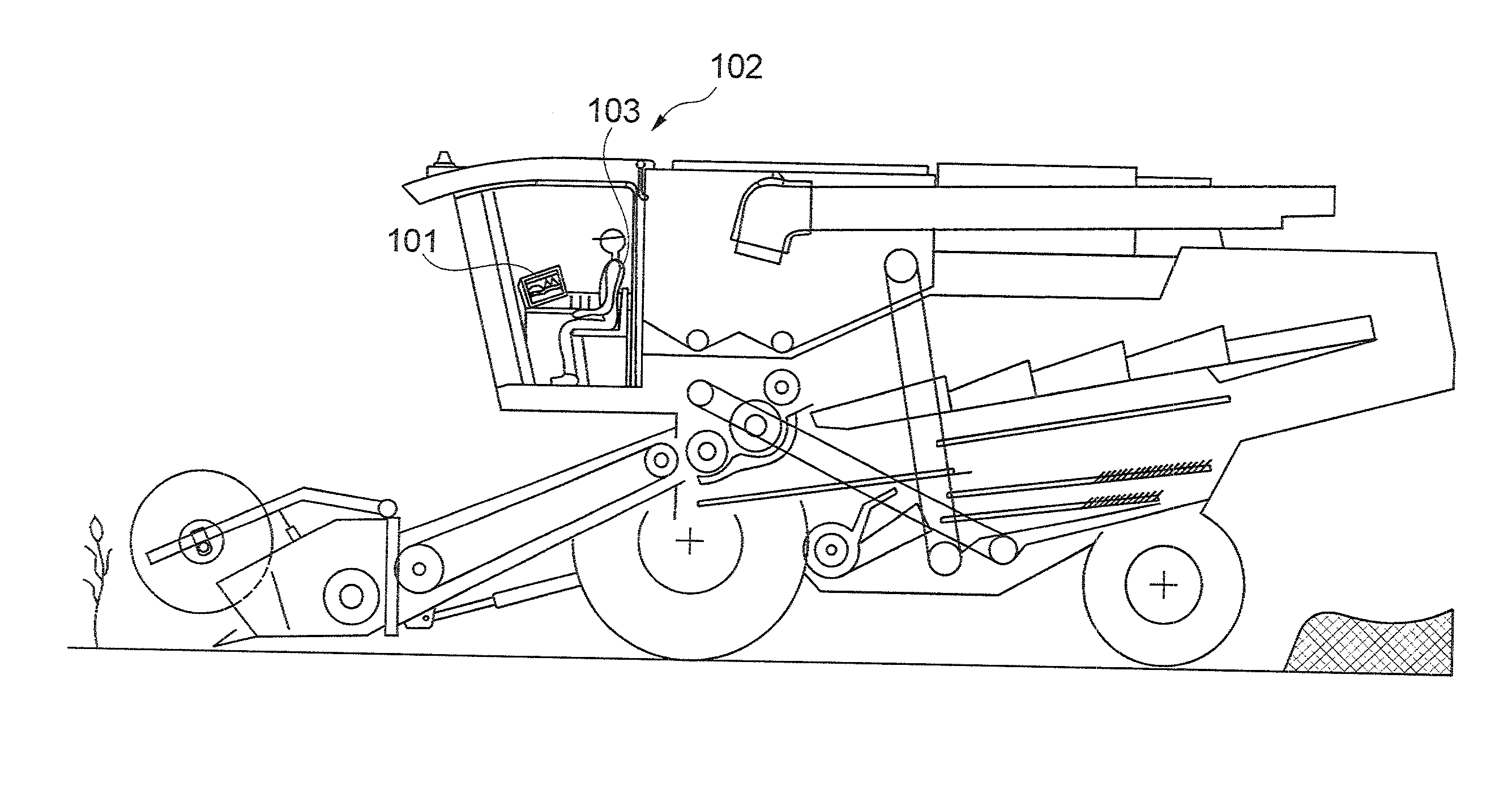
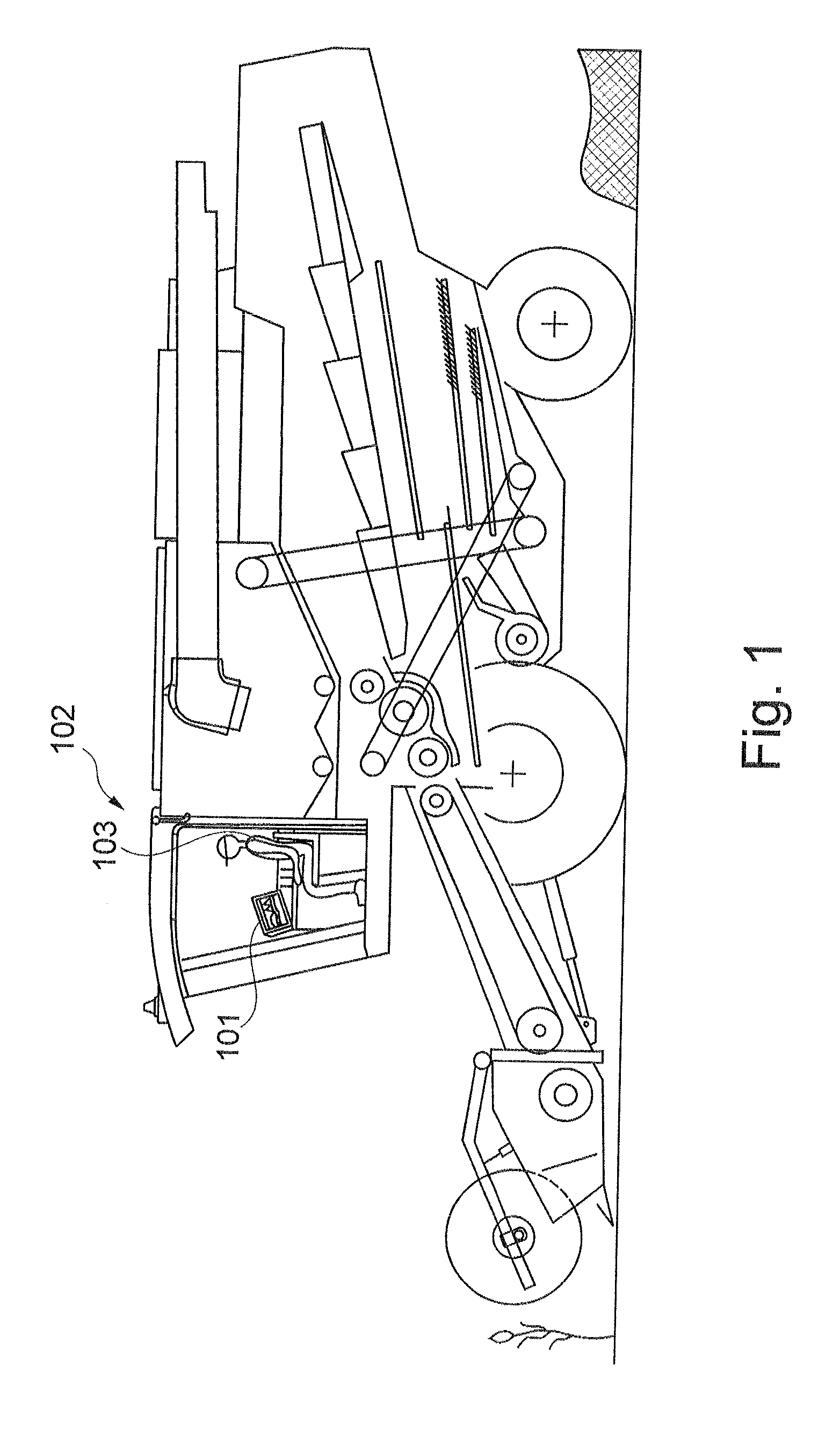
[0034]FIG. 1 shows an agricultural working machine designed as a combine harvester, and its various working units. The agricultural machine includes a driver's cab 102, in which driver 103 sits while driving the agricultural machine. A display device 101 which may optically show driver 103 the status of the operating parameters of the agricultural machine is located in the driver's cab. Driver 103 may perform a controlling maneuver of the agricultural machine based on this optical depiction. Display device 101 may include one or more display units according to the present invention.

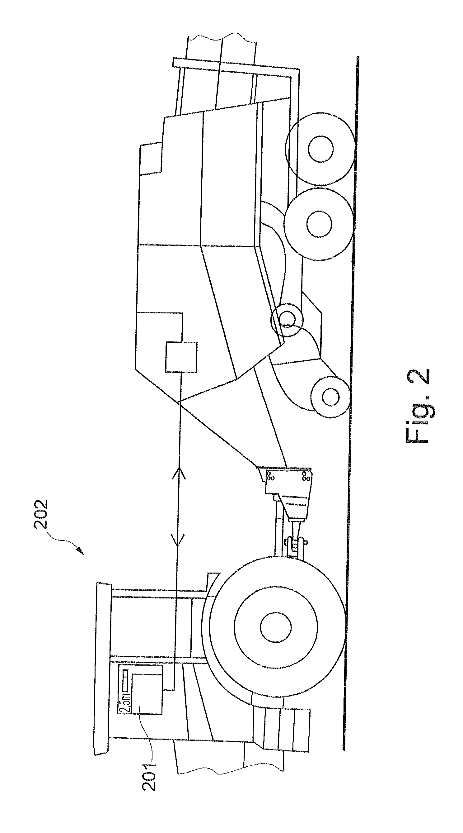
[0035]FIG. 2 shows a tractor which includes an adapted agricultural baler as an additional working unit. The tractor includes a driver's cab 202; a display device 201 is located in driver's cab 202. A part of the display device may be a display unit according to the present invention.

[0036]FIG. 3 shows a display device which also includes operating elements 304, 305 which are located on a control panel 30...


PUM


Abstract

A display device for displaying operating parameters of an agricultural machine which includes a working unit has a display unit designed such that it may display several subsections, to each of which an operating parameter is assigned, in a first operating state of the working unit, a closed main region having a central geometric focal point may be displayed, and a first subsection is limited on the side by a second subsection, in a second operating state of the working unit, the mean distance between one side of the first subsection and the central geometric focal point is changed, and an agricultural machine includes the working unit, a driver's cab, and the display device.

Description

CROSS-REFERENCE TO A RELATED APPLICATION[0001]The invention described and claimed hereinbelow is also described in German Patent Application DE 10 2008 057 461.9 filed on Nov. 14, 2008. This German Patent Application, whose subject matter is incorporated here by reference, provides the basis for a claim of priority of invention under 35 U.S.C. 119(a)-(d).BACKGROUND OF THE INVENTION[0002]The present invention relates to a display device with a display unit for displaying operating parameters of an agricultural machine which includes a working unit, and to an agricultural machine which includes a working unit and a driver's cab and has a display device.[0003]Publication EP 1 650 715 B1 discloses a display system which, depending on which menu level is selected, displays a large number of operating parameters, such as ground speed, fuel consumption, crop material throughput, and the height of a header above the ground.[0004]An operator of an agricultural machine is shown a large number...

Claims


Application Information

Patent Timeline
Patent Type & Authority Patents(United States)
IPC IPC(8): G06F3/01
CPCA01D41/127
Inventor HIERONYMUS, PETERLAING, REINHARDROEMER, JENSGREWINGA, MARKUS
Owner CLAAS SELBSTFAHRENDE ERNTEMASCHINEN GMBH
Why Eureka
Try Eureka