Luminaire having light-emitting elements disposed on protrusions

a technology of light-emitting elements and protrusions, which is applied in the field of luminaires, can solve the problems of limited and achieve the effect of easy heat dissipation and increased view angle of luminaires

Inactive Publication Date: 2013-04-16
LITE ON ELECTRONICS (GUANGZHOU) LTD +1
View PDF4 Cites 21 Cited by
  • Summary
  • Abstract
  • Description
  • Claims
  • Application Information

AI Technical Summary

Benefits of technology

[0006]The object of this invention is to provide a luminaire capable of increasing the view angle.
[0008]The luminaire of this invention has an effect in that, due to disposition of the first light-emitting modules on the inclined surfaces of the protrusions, the view angle of the luminaire can be increased. Furthermore, since the first light-emitting elements are disposed on the protrusions, heat can be dissipated easily from the first light-emitting modules.

Problems solved by technology

Although LEDs (light emitting diodes) have the advantages of low power consumption and high efficiency, the view angle thereof is limited.
As a result, when LEDs are employed in a luminaire (such as a bulb) to serve as light sources, the view angle of the luminaire is also limited.

Method used


Image

  • Luminaire having light-emitting elements disposed on protrusions
  • Luminaire having light-emitting elements disposed on protrusions
  • Luminaire having light-emitting elements disposed on protrusions

Examples


Embodiment Construction

[0016]Before the present invention is described in greater detail in connection with the preferred embodiments, it should be noted that similar elements and structures are designated by like reference numerals throughout the entire disclosure.

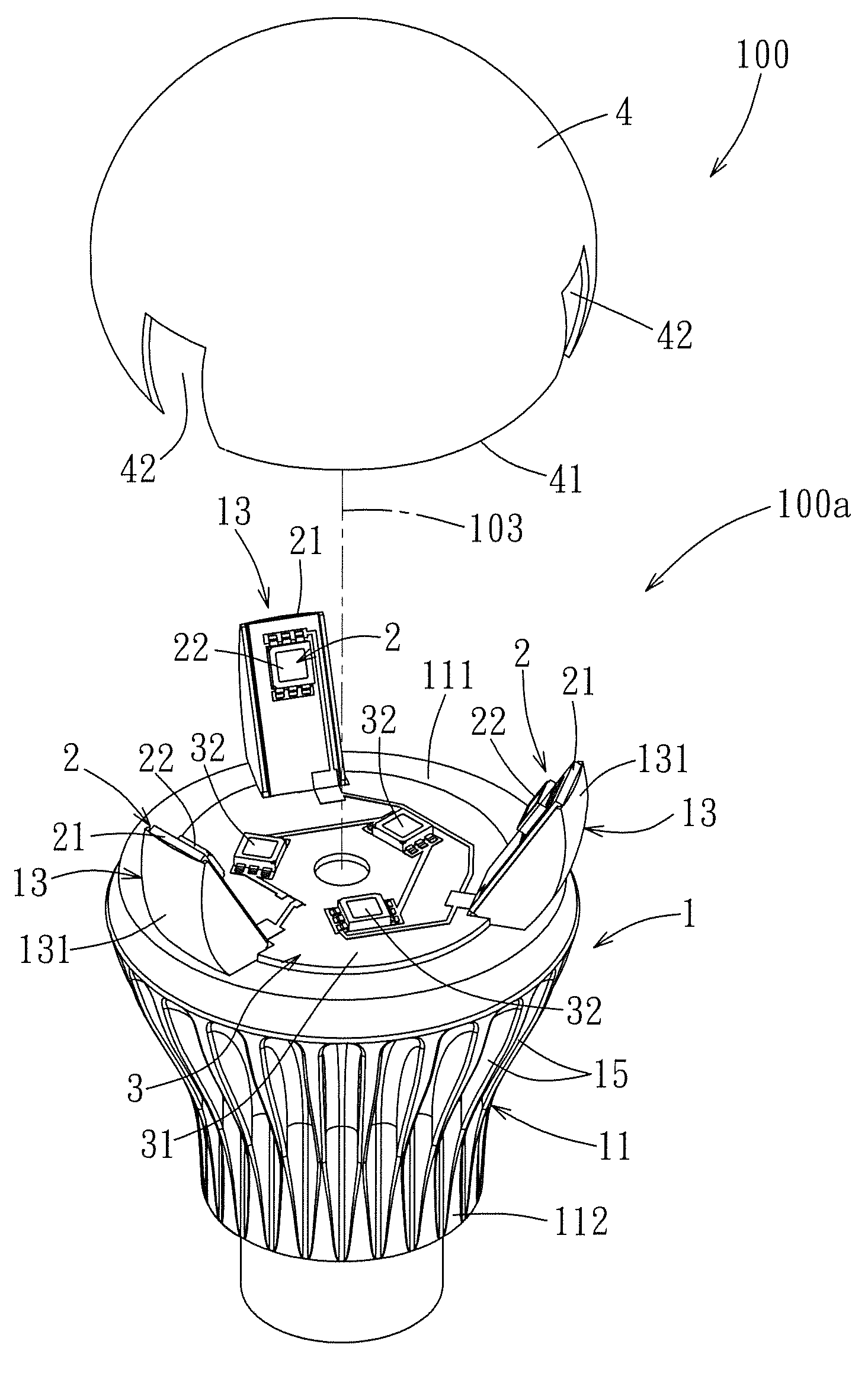
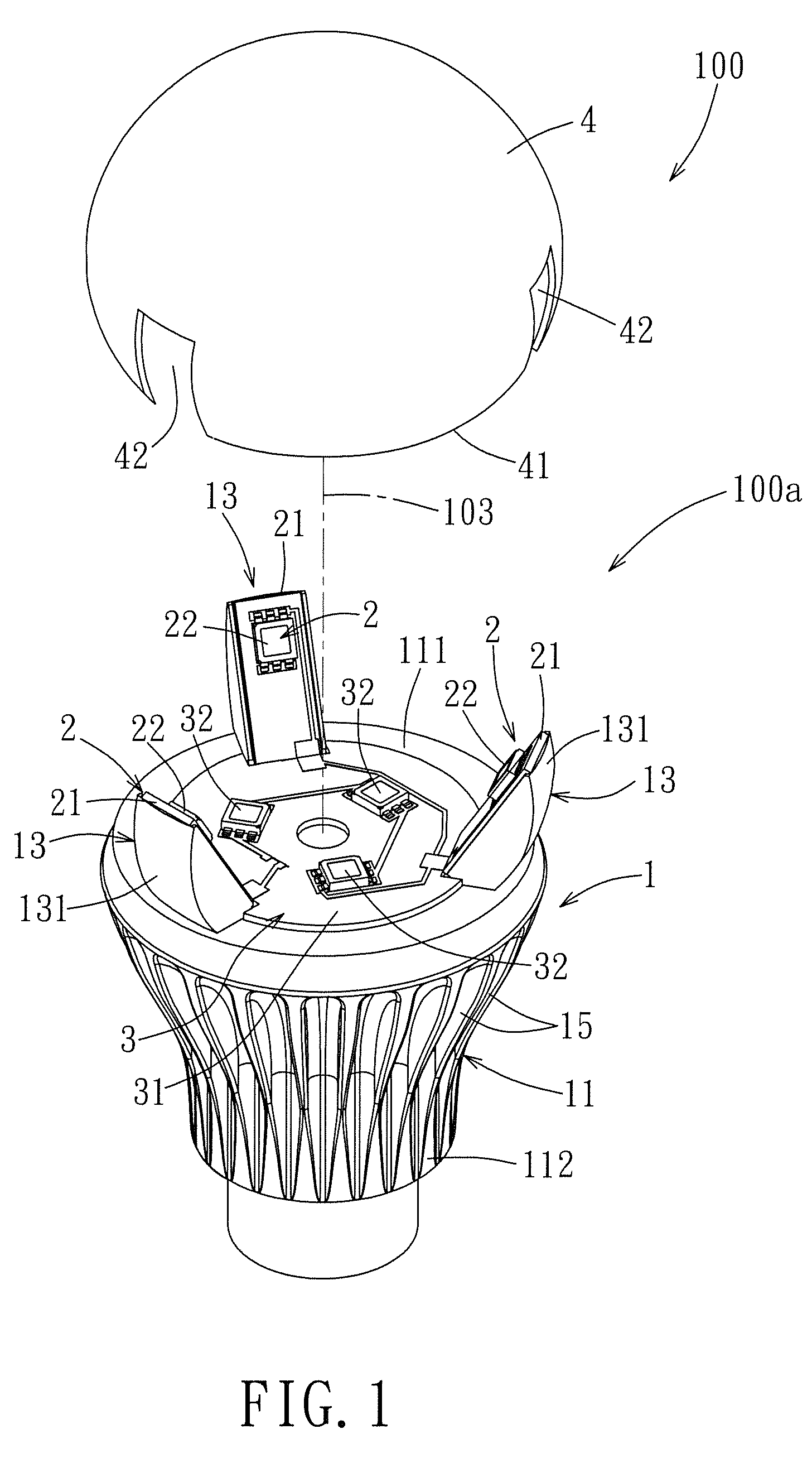
[0017]Referring to FIGS. 1, 2, and 3, the first preferred embodiment of a luminaire 100 according to this invention includes a lamp holder module 100a, a plurality of first light-emitting modules 2, and a second light-emitting module 3.

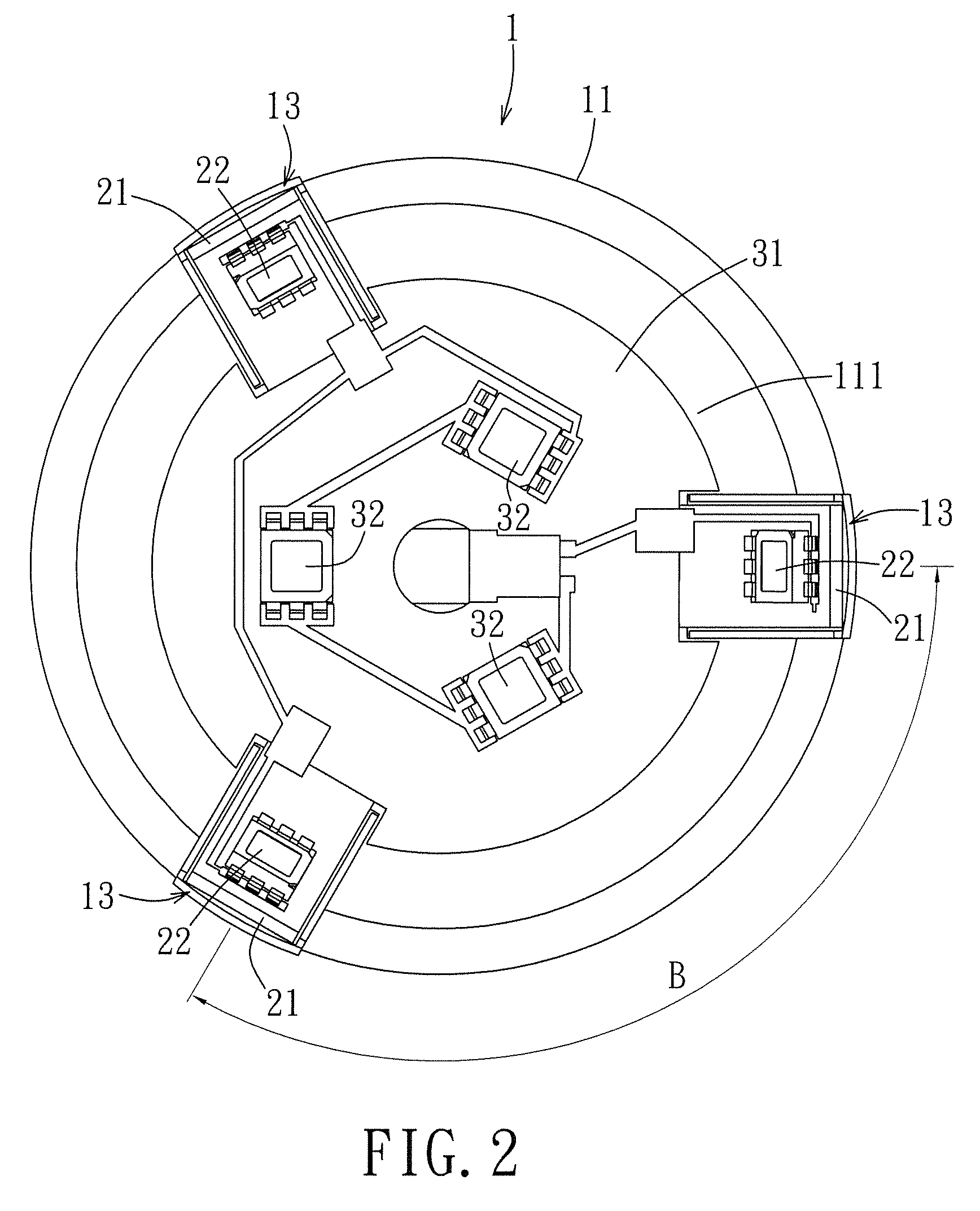
[0018]The lamp holder module 100a includes a lamp holder 1 and a lamp cover 4. The lamp holder 1 includes a holder body 11 and a plurality of protrusions 13. The holder body 11 has a top surface 111, an outer peripheral surface 112 extending downwardly from an outer periphery of the top surface 111, a central axis 103 extending uprightly through the top surface 111, and a plurality of heat-dissipating fins 15 formed on the outer peripheral surface 112. In this embodiment, the number of the protrusions 13 is but n...


PUM


Abstract

A luminaire includes a lamp holder, a lamp cover and a plurality of first light-emitting modules. The lamp holder has a top surface, a plurality of protrusions protruding upwardly from the top surface. Each of the protrusions has an inclined surface. The lap cover is connected to the lamp holder, and covers the top surface and the inclined surfaces. Each of the first light-emitting modules includes a first light-emitting element. The view angle of the luminaire can be increased due to disposition of the first light-emitting elements on the inclined surfaces of the protrusions. Furthermore, since the first light-emitting elements are disposed on the protrusions, heat can be dissipated easily from the first light-emitting elements.

Description

CROSS-REFERENCE TO RELATED APPLICATION[0001]This application claims priority of U.S. provisional application No. 61 / 375,350, filed on Aug. 20, 2010, and Chinese Application No. 201110005182.8, filed on Jan. 6, 2011.BACKGROUND OF THE INVENTION[0002]1. Field of the Invention[0003]This invention relates to a luminaire, and more particularly to a luminaire capable of increasing the view angle.[0004]2. Description of the Related Art[0005]Although LEDs (light emitting diodes) have the advantages of low power consumption and high efficiency, the view angle thereof is limited. As a result, when LEDs are employed in a luminaire (such as a bulb) to serve as light sources, the view angle of the luminaire is also limited.SUMMARY OF THE INVENTION[0006]The object of this invention is to provide a luminaire capable of increasing the view angle.[0007]Accordingly, the luminaire of this invention includes a lamp holder, a lamp cover and a plurality of first light-emitting modules. The lamp holder has...

Claims


Application Information

Patent Timeline
Patent Type & Authority Patents(United States)
IPC IPC(8): H01J5/48
CPCF21K9/135F21V29/773F21V29/75F21V29/77F21V3/02F21Y2101/02F21Y2111/001F21K9/232F21Y2107/00F21Y2115/10F21K9/235F21K9/237
Inventor LIANG, CHIH-LUNGYANG, SHU-HUACHENG, CHIN-MINGTSAI, JUI-LIN
Owner LITE ON ELECTRONICS (GUANGZHOU) LTD
Why Eureka
Try Eureka