Surgical stapling instrument with improved firing trigger arrangement
What is AI technical title?
AI technical title is built by Patsnap AI team. It summarizes the technical point description of the patent document.
a technology of firing trigger and stapling instrument, which is applied in the direction of surgical staples, surgical forceps, paper/cardboard containers, etc., can solve the problems of inability to move the anvil and the inability to adjust the formed height of the staples
Active Publication Date: 2013-06-04
CILAG GMBH INT
View PDF1446 Cites 1481 Cited by
Summary
Abstract
Description
Claims
Application Information
AI Technical Summary
This helps you quickly interpret patents by identifying the three key elements:
Problems solved by technology
Method used
Benefits of technology
Benefits of technology
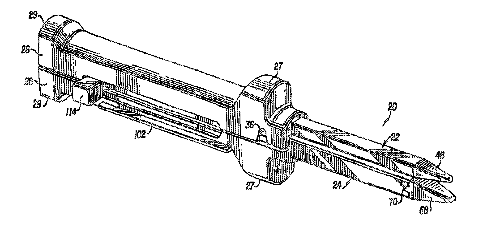
[0009]In at least one form, a surgical stapling instrument can comprise a first side, a second side, a longitudinal axis, a first housing member, and a second housing member. The first housing member can comprise a staple cartridge attachment portion configured to operably support a staple cartridge, and a first lock rail extending along the longitudinal axis. The second housing member can comprise a jaw member configured to operably support an anvil configured to deform staples deployed from the staple cartridge, and a second lock rail extending along the longitudinal axis. The surgical stapling instrument can further comprise a pusher bar configured to move a staple driver relative to the staple cartridge attachment portion and the jaw member, and an actuator configured to receive a force thereto, wherein the actuator is configured to be moved between a first position and a second position, wherein the actuator is configured to be moved along the first side when said actuator is in the first position, wherein the actuator is configured to be moved along the second side when the actuator is in the second position, and wherein the actuator further comprises capturing means for capturing the first lock rail and the second lock rail.
Problems solved by technology
In typical stapling instruments, however, the anvil is unmovable relative to the staple cartridge once the jaw members have been assembled together and the formed height of the staples cannot be adjusted.
Method used
Image
Click on the blue label to locate the original text in one second.
Reading with bidirectional positioning of images and text.
Examples
example 1
[0256]A surgical staple can be deformed such that:
[0257]
First LegSecond LegCrosses the midline (FIG. 83)Crosses the midline (FIG. 83)Extends in-plane, or substantiallyExtends out of plane within-plane, with the base (FIG. 91)the base (FIG. 85)The end extends in a non-per-The end extends in a non-per-pendicular direction with thependicular direction with thebaseline (FIG. 83)baseline (FIG. 83)
example 2
[0258]A surgical staple can be deformed such that:
[0259]
First LegSecond LegCrosses the midline (FIG. 83)Crosses the midline (FIG. 83)Extends out of plane with the baseExtends out of plane with the base(FIG. 85) to the same side of the(FIG. 85) to the same side of thebase as the second leg, the distancebase as the first leg, the distanceX1 being different than X2X1 being different than X2(FIG. 85A)(FIG. 85A)The end extends in a non-The end extends in a non-perpendicular direction withperpendicular direction withthe baseline (FIG. 83)the baseline (FIG. 83)
example 3
[0260]A surgical staple can be deformed such that:
[0261]
First LegSecond LegDoes not cross the midlineDoes not cross the midline(FIG. 90)(FIG. 90)Extends out of plane with theExtends out of plane with the basebase (FIG. 85) to a first side of(FIG. 85) to a second side ofthe base, the distance X1 beingthe base, the distance X1 beingdifferent than X2 (FIG. 85A)different than X2 (FIG. 85A)The end extends in aThe end extends in anon-perpendicular directionnon-perpendicular directionwith the baseline (FIG. 83)with the baseline (FIG. 83)
PUM
Property
Measurement
Unit
angle
aaaaa
aaaaa
angle
aaaaa
aaaaa
angle
aaaaa
aaaaa
Abstract
A surgical stapling instrument including an actuator knob which can be moved from one side of the stapling instrument to another side in order to reposition the actuator knob without having to reposition the stapling instrument within a surgical site. A stapling instrument can include a pusher bar, a housing having a first side and a second side, and an actuator knob rotatably mounted to the pusher bar wherein the actuator knob can be configured to be rotated between a first position in which the actuator knob can be moved along the first side of the housing and a second position where the actuator knob can be moved along a second side of the housing. Alternatively, a surgical stapling instrument can comprise one or more actuator knobs which can be operably engaged and disengaged with a pusher bar in order to selectively utilize the actuator knobs.
Description
CROSS-REFERENCE TO RELATED APPLICATIONS[0001]This non-provisional patent application is a continuation-in-part application under 35 U.S.C. §120 of U.S. patent application Ser. No. 12 / 725,993, entitled STAPLE CARTRIDGE, filed on Mar. 17, 2010, now U.S. Publication No. 2010 / 0213241 A1 , which is a continuation-in-part application under 35 U.S.C. §120 of U.S. patent application Ser. No. 12 / 234,149, entitled SURGICAL STAPLING INSTRUMENT WITH CUTTING MEMBER ARRANGEMENT, filed on Sep. 19, 2008, now U.S. Pat. No. 7,905,381, the entire disclosures of which are hereby incorporated by reference herein. This non-provisional patent application is a continuation-in-part application under 35 U.S.C. §120 of U.S. patent application Ser. No. 12 / 622,099, entitled SURGICAL STAPLER HAVING A CLOSURE MECHANISM, filed on Nov. 19, 2009, now U.S. Publication No. 2011 / 0084115 A1, which claims the benefit under 35 U.S.C. §119(e) of U.S. Provisional Patent Application No. 61 / 250,377, entitled SURGICAL STAPLER,...
Claims
Application Information
Patent Timeline
Application Date:The date an application was filed.
Publication Date:The date a patent or application was officially published.
First Publication Date:The earliest publication date of a patent with the same application number.
Issue Date:Publication date of the patent grant document.
PCT Entry Date:The Entry date of PCT National Phase.
Estimated Expiry Date:The statutory expiry date of a patent right according to the Patent Law, and it is the longest term of protection that the patent right can achieve without the termination of the patent right due to other reasons(Term extension factor has been taken into account ).
Invalid Date:Actual expiry date is based on effective date or publication date of legal transaction data of invalid patent.

