Image forming apparatus provided with post-processing device

a technology of post-processing and forming apparatus, which is applied in the direction of electrographic process apparatus, digital output to print units, instruments, etc., can solve the problems of hindering user workability and difficulty in dealing with tasks, and achieve the effect of improving workability and visibility

Active Publication Date: 2013-07-16
SHARP KK
View PDF11 Cites 1 Cited by
  • Summary
  • Abstract
  • Description
  • Claims
  • Application Information

AI Technical Summary

Benefits of technology

[0007]The present invention is directed to providing an image forming apparatus that is capable of providing improved workability at an intra-body paper discharge section by lighting up the intra-body paper discharge section with a light source, while preventing direct projection light of a light source from coming into a user's sight.
[0009]Because the objective working section is lit up in the intra-body paper discharge section by the light source, brightness of the objective working section increases, visibility improves, and then workability to the objective working section improves. On the other hand, because the shade member is disposed in the front face side from the light source, the direct projection light to the front side of the light source is blocked.

Problems solved by technology

On this account, there have been problems associated with difficulties in dealing with tasks such as retrieval of recording media at the intra-body paper discharge section, and / or maintenance tasks to the post-processing device, etc.
Sight of such direct projection light would dazzle the user, and then rather be likely to hinder the user's workability.

Method used


Image

  • Image forming apparatus provided with post-processing device
  • Image forming apparatus provided with post-processing device
  • Image forming apparatus provided with post-processing device

Examples


Embodiment Construction

[0019]An embodiment of the present invention is explained below based on the drawings.

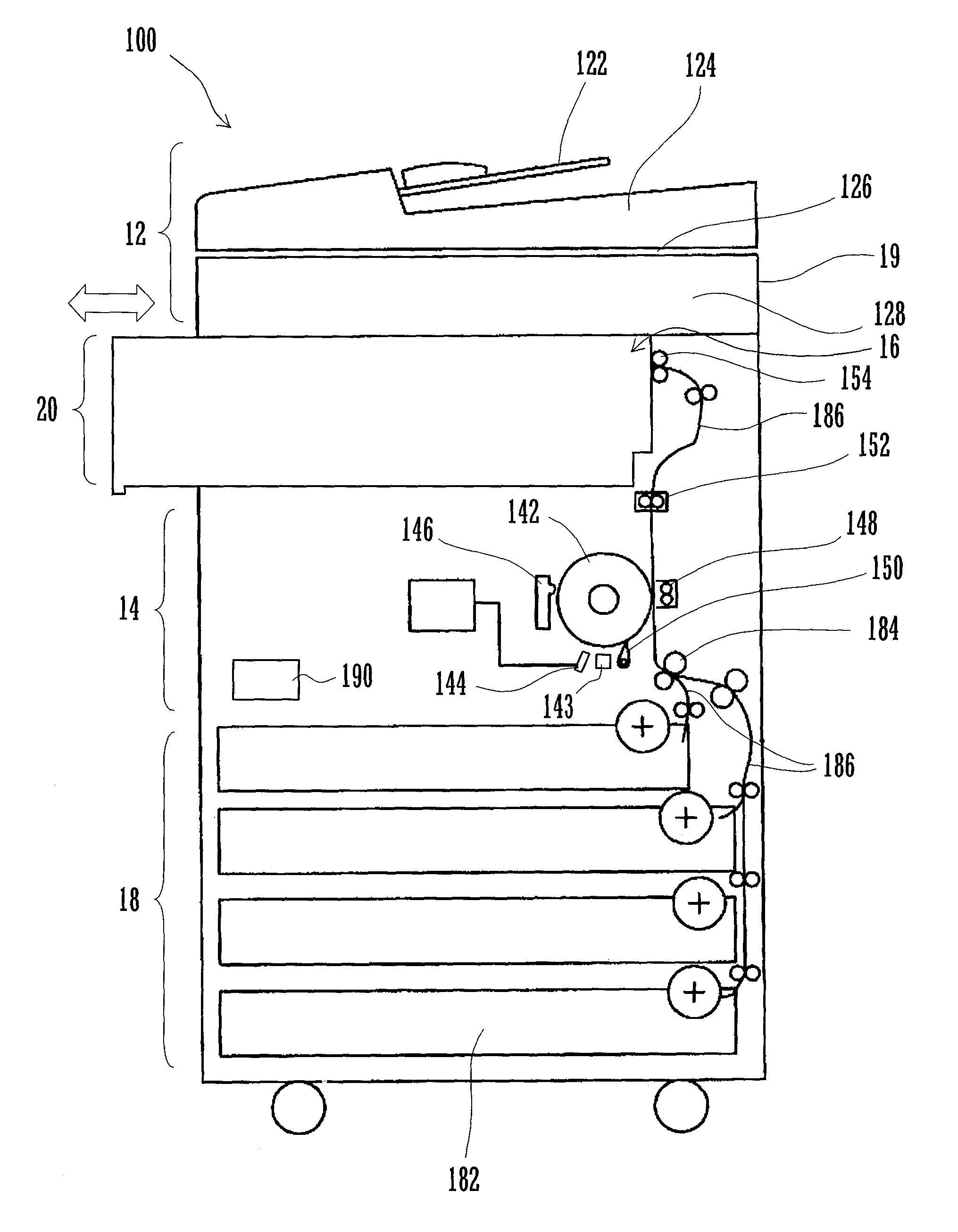
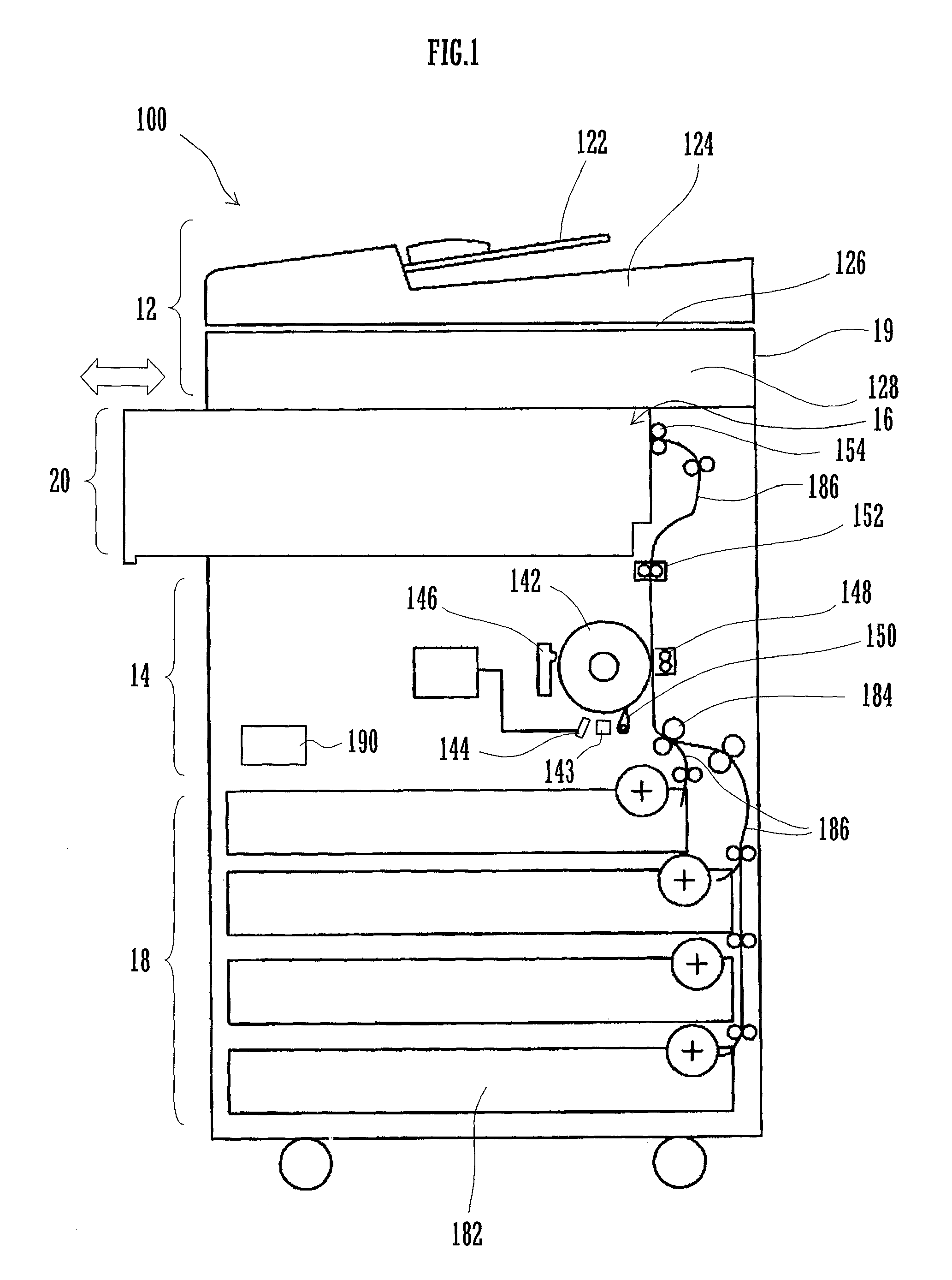
[0020]As shown in FIG. 1, an image forming apparatus 100 comprises: a main body 19 including an image reading section 12 for reading an image of a document and generating a set of image data, an image forming section 14 for performing an image forming process on paper, and a paper supply section 18 for supplying paper to the image forming section 14 sequentially; and a post-processing device 20 for performing a post-process on the paper as an example of a recording medium to which an image forming process has been applied at the image forming section 14. The image forming apparatus 100 is generally controlled by a control section 190.

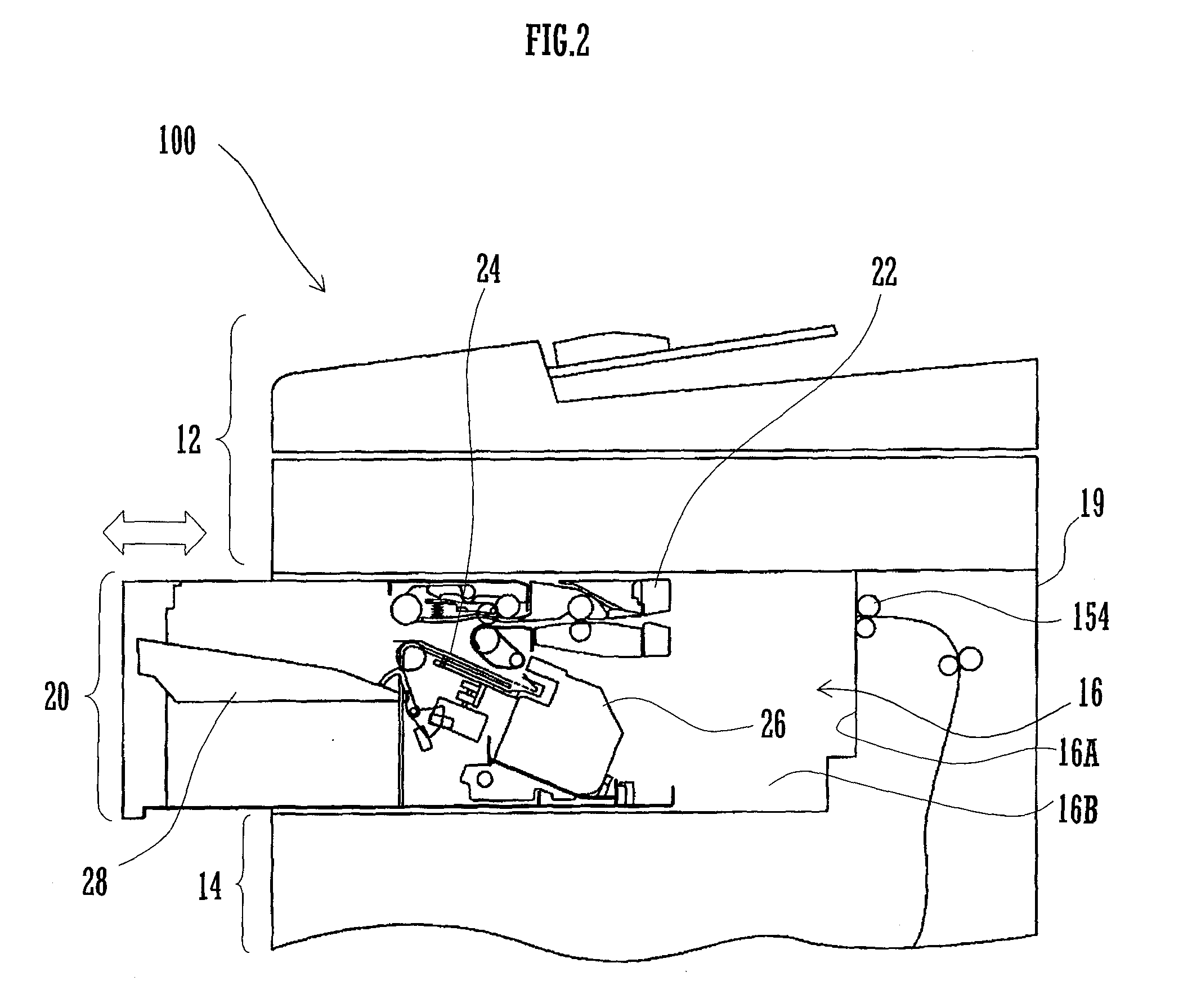
[0021]An intra-body paper discharge section 16 is provided in a space sandwiched between upside and downside by the image reading section 12 and the image forming section 14 respectively.

[0022]The image reading section 12 comprises an optical system unit 128 configured...


PUM


Abstract

An image forming apparatus comprises a main body, a post-processing device, an objective working section, a light source and a shade member. The post-processing device is disposed freely displaceable between a retracted position at which it is received by an intra-body paper discharge section of the main body and a protruded position at which it is drawn to one side face side. The objective working section is disposed on an upstream side face of the post-processing device in the drawing direction of the post-processing device.The light source is disposed on the upstream side face of the post-processing device, and lights up the objective working section at the protruded position. The shade member is disposed on the upstream side face of the post-processing device and in the front face side from the light source, and blocks direct projection light of the light source to the front face side.

Description

CROSS REFERENCE[0001]This Nonprovisional application claims priority under 35 U.S.C. §119(a) on Patent Application No. 2009-199922 filed in Japan on Aug. 31, 2009, the entire contents of which are hereby incorporated by reference.BACKGROUND OF THE INVENTION[0002]The present invention relates to an image forming apparatus comprising a post-processing device that is disposed so as to be freely displaceable between the retracted position and protruded position thereof at an intra-body paper discharge section which is sandwiched between upside and downside by an image reading section and an image forming section respectively.[0003]In recent years, as demand for a smaller-sized image forming apparatus has increased, what is called intra-body paper discharge models of image forming apparatus have been used, wherein recording media having undergone an image forming process are discharged to a paper discharge section that is disposed inside the body and sandwiched between upside and downsid...

Claims


Application Information

Patent Timeline
Patent Type & Authority Patents(United States)
IPC IPC(8): G06F3/12G03G15/00
CPCG03G15/6552
Inventor MATSUMOTO, YOSHITAKATSUJI, MASARU
Owner SHARP KK
Why Eureka
Try Eureka