Combined wing scan and winglet illumination light unit and aircraft having winglet illumination

a technology of winglet illumination and light unit, which is applied in the field of exterior aircraft lighting, can solve the problems of lack of efficient technology for illuminating the winglet, and achieve the effect of improving the efficiency of winglet illumination

Active Publication Date: 2015-02-17
GOODRICH LIGHTING SYST
View PDF7 Cites 14 Cited by
  • Summary
  • Abstract
  • Description
  • Claims
  • Application Information

AI Technical Summary

Problems solved by technology

However, no efficient technology for illumin

Method used


Image

  • Combined wing scan and winglet illumination light unit and aircraft having winglet illumination
  • Combined wing scan and winglet illumination light unit and aircraft having winglet illumination
  • Combined wing scan and winglet illumination light unit and aircraft having winglet illumination

Examples


Embodiment Construction

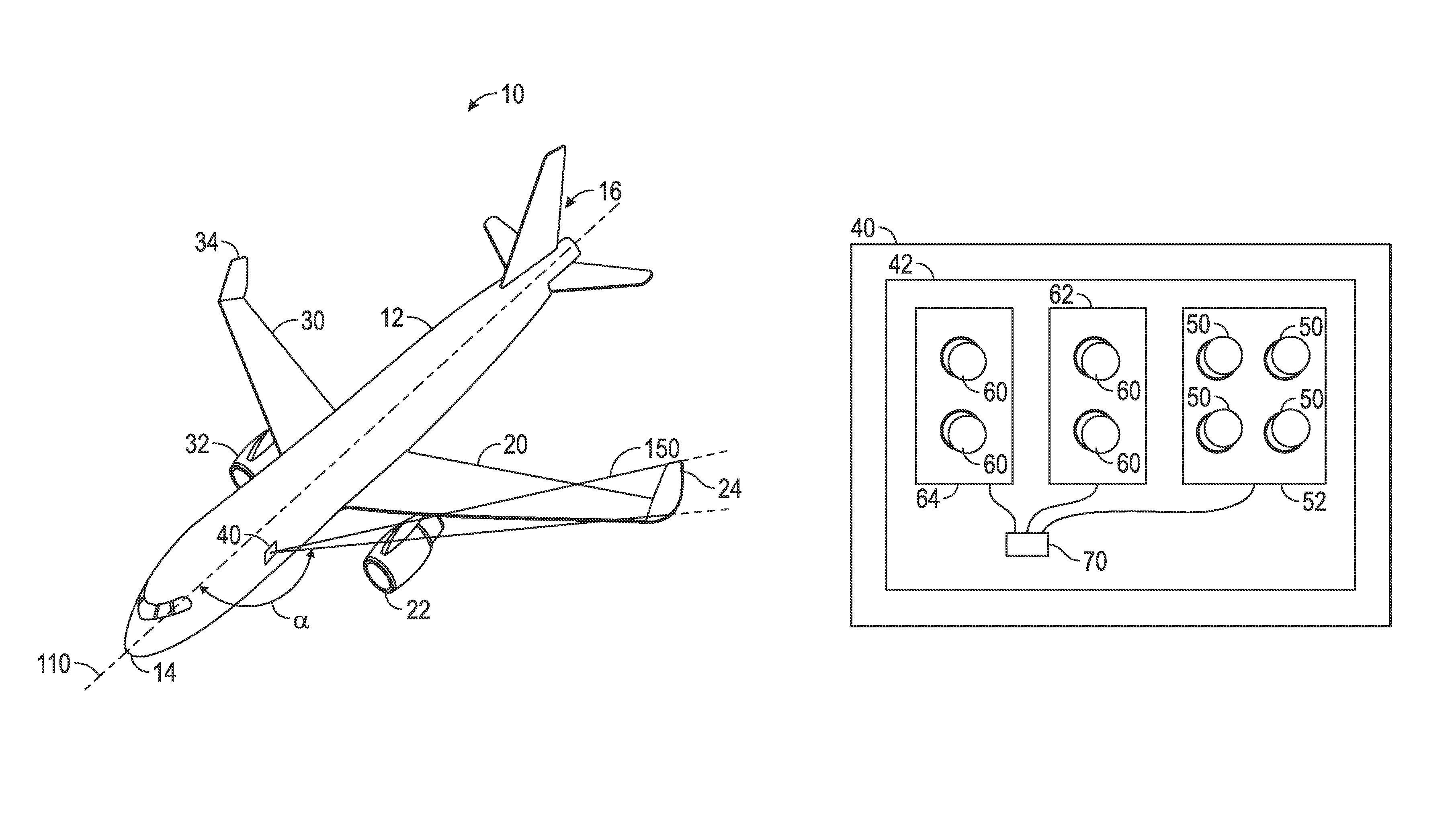
[0014]FIG. 1 shows an aircraft 10 in a perspective view in accordance with an exemplary embodiment of the invention. The aircraft 10 has a fuselage 12, extending from a nose 14 of the aircraft to a tail 16 of the aircraft. Attached to the fuselage 12, there are provided a left wing 20 and a right wing 30. The left wing 20 carries a left engine 22, while the right wing 30 carries a right engine 32. The left and right engines 22 and 32 are commonly gas turbine engines, but the invention is not restricted thereto.

[0015]The left wing 20 has a left wing tip winglet 24, which extends substantially upwards from the remainder of the left wing 20. The right wing 30 has a right wing tip winglet 34, which extends substantially upwards from the remainder of the right wing 30. The wing tip winglets 24 and 34 are provided at the end of the respective wing. The left and right wings 20 and 30 have an airfoil section, extending between the fuselage 12 and the respective winglets 24 and 34, with the ...


PUM


Abstract

A combined wing scan and winglet illumination light unit is disclosed. The light unit has at least one LED and at least one optical structure for shaping a light emission distribution of the combined wing scan and winglet illumination light unit. The wherein the light emission distribution has a first illumination region for illuminating a wing and a wing engine of an aircraft and a second illumination region for illuminating a wing tip winglet of the aircraft.

Description

BACKGROUND OF THE INVENTION[0001]The present invention is in the field of exterior aircraft lighting. More particularly, the present invention is concerned with those exterior aircraft light units that illuminate the aircraft itself.[0002]Exterior aircraft lighting serves a wide range of purposes. On the one hand, there is safety-critical lighting, such as position signalling and take-off / landing lighting. On the other hand, certain lights are provided for marketing purposes. An example of such a light is a fin illumination light, illuminating the vertical structure at the tail of the plane, which is usually provided with the airline's logo.[0003]Modern airplanes increasingly have so-called winglets at the ends of their wings. These winglets are wing tip structures that are angled with respect to the wing profile and extend generally upwards. On the one hand, such winglets reduce lift induced drag caused by wing tip vortices. On the other hand, such winglets also provide an area of ...

Claims


Application Information

Patent Timeline
IPC IPC(8): B64D47/02
CPCB64D47/02
Inventor HESSLING VON HEIMENDAHL, ANDREKLEIN, FRANKLUEDER, SASCHA
Owner GOODRICH LIGHTING SYST
Why Eureka
Try Eureka