Device and method for applying a medical lockable clip in a tissue area

a technology of lockable clips and devices, applied in the direction of rail fasteners, surgical staples, ways, etc., can solve the problems of poor placement of clips, and achieve the effect of reliable and reproducible placement of such clips

Active Publication Date: 2016-09-06
KARLSRUHER INST FUR TECH +1
View PDF54 Cites 1 Cited by
  • Summary
  • Abstract
  • Description
  • Claims
  • Application Information

AI Technical Summary

Benefits of technology

[0004]A basic object of the present invention is therefore to provide a device and a method of the type mentioned in the introduction, which device and method make possible the reliable and reproducible placement of such clips in body tissues.
[0008]It is achieved by the present invention that the clip can be shot into and closed in a certain tissue with equal force, so that equal, reproducible results can also be obtained. In addition, it becomes possible to use different shoot-in forces in tissues having different firmness or hardnesses in order to achieve reliable fixation of the clip even independently from the consistency of the tissue. In addition, both a higher shoot-in velocity and a stronger closing force can be applied through the present invention than it would be possible manually, as a result of which the fixation of the clip is likewise improved. The device may have a positive-locking or frictionally engaged mount for the clip, the locking element having a toggle lever element, which presses the gripping teeth of the clip against each other and releases the positive-locking and / or frictionally engaged mount of the clip. Provisions are made in a preferred embodiment for the mount to hold the clip preferably in a positive-locking manner by nubs, which mesh for locking the clip with corresponding nubs or depressions, which are formed in the clip mount, being provided laterally at the clip or the tooth flanks thereof. The positive-locking connection can be abolished by the change in the shape of the clip during the actuation of the toggle lever mechanism.

Problems solved by technology

The drawback of the prior-art device is that the force for shooting in and closing the clip must be applied manually and the operation does not therefore lead to reliably reproducible, identical results; poor placement of the clip may at times occur as well.

Method used


Image

  • Device and method for applying a medical lockable clip in a tissue area
  • Device and method for applying a medical lockable clip in a tissue area
  • Device and method for applying a medical lockable clip in a tissue area

Examples


Embodiment Construction

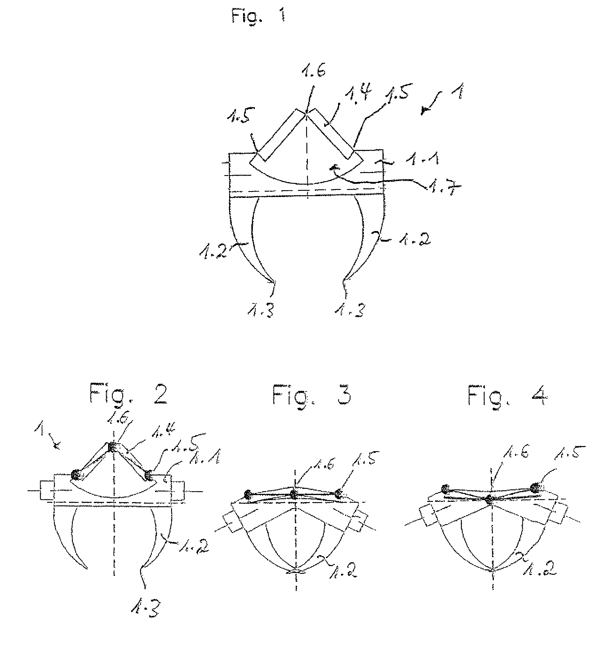
[0031]Referring to the drawings in particular, the resorbable clip used according to the present invention has centrally a deformable shoulder 1.1, on one side of which clip a tooth 1.2 each with a sharp tip 1.3 is formed at the end areas on one side of the clip.

[0032]On the side of the shoulder 1.1 located opposite the teeth 1.2, a toggle lever 1.4 is likewise formed in one piece, which is connected to the shoulder 1.1 via film hinges 1.5 and the two parts of which are likewise connected centrally to one another via a film hinge 1.6.

[0033]Under the toggle lever 1.4, the shoulder has a recess 1.7, into which the toggle lever 1.4 can be used in the overstretched position. The deformable shoulder 1.1, the toggle lever 1.4, the film hinges 1.5 and 1.6 and the recess 1.7 provide a clip-side locking mechanism.

[0034]FIGS. 1 and 2 show the clip 1 in the unloaded starting or standby position thereof with the teeth 1.3 opened. FIG. 3 shows a configuration of clip 1, in which a force is appli...


PUM


Abstract

A device and method are provided for clips or staples as an effective substitute for suture material when joining body tissue or covering body tissue with a mesh, such as is particularly used in fracture operations. The device for applying a medical lockable clip (1) in a tissue area, includes a) an automatic advancing mechanism oriented in the direction of the tissue area from a starting position and having a guide in the advancing direction for the clip, wherein the clip has two gripper teeth oriented in the advancing direction, b) a stop for the advancing mechanism, and c) a locking element displaceable with the advancing mechanism and having a locking mechanism on the clip side for locking the clip, wherein d) the locking element is displaceable together with and parallel to the advancing mechanism, and e) the stop does not limit the motion of the locking element.

Description

CROSS REFERENCE TO RELATED APPLICATIONS[0001]This application is a United States National Phase application of International Application PCT / EP2010 / 003166 and claims the benefit of priority under 35 U.S.C. §119 of German Patent Application DE 10 2009 022 692.3 filed May 26, 2009, the entire contents of which are incorporated herein by reference.FIELD OF THE INVENTION[0002]The present invention pertains to a device and a method for applying a medical lockable clip in a tissue area.BACKGROUND OF THE INVENTION[0003]Such a device is known from EP 1 199 990 B1. The drawback of the prior-art device is that the force for shooting in and closing the clip must be applied manually and the operation does not therefore lead to reliably reproducible, identical results; poor placement of the clip may at times occur as well.SUMMARY OF THE INVENTION[0004]A basic object of the present invention is therefore to provide a device and a method of the type mentioned in the introduction, which device and ...

Claims


Application Information

Patent Timeline
Patent Type & Authority Patents(United States)
IPC IPC(8): A61B17/10A61B17/068A61B17/08A61B17/064A61B17/00
CPCA61B17/0682A61B17/0644A61B17/08A61B17/10A61B17/105A61B2017/00539A61B2017/00544A61B17/12E01B9/30
Inventor KNEIFEL, BERNHARDKORBER, RAINERHERRMANN, GUNTERBRHEL, KLAUS-PETERNOTHEIS, EKATERINARIES, WOLFGANG
Owner KARLSRUHER INST FUR TECH
Why Eureka
Try Eureka