Display with a supporting mechanism

a technology of supporting mechanism and display module, which is applied in the field of display, can solve the problems of user inconvenience to a certain extent, user inconvenience, and user inconvenience, and achieve the effect of facilitating the use of the display module and stable carrying or holding

Active Publication Date: 2017-09-26
QISDA SUZHOU +1
View PDF5 Cites 3 Cited by
  • Summary
  • Abstract
  • Description
  • Claims
  • Application Information

AI Technical Summary

Benefits of technology

[0005]An objective of the invention is to provide a display with a supporting mechanism. The supporting mechanism uses a rotatable support to provide both supporting function and carrying function. When in a carrying state, the rotatable support can prevent the display from turning relative to the supporting device, so that a user can stably carry or hold the display through the supporting mechanism.
[0006]A display with a supporting mechanism according to the invention includes a portable electronic display module and a supporting device connecting the display module. The supporting device includes a base and a rotatable support. The base is used for fixing the display module and includes a first constraint structure. The rotatable support includes a rotation member, a handle, and a connection member. The rotation member is pivotally connected to the base. The handle is pivotally connected to the rotation member through the connection member, so that the handle can rotate toward and away from the base. The connection member includes a second constraint structure engaged with or disengaged from the first constraint structure. Therein, when the rotation member is located at a position relative to the base, the first constraint structure and the second constraint structure are engaged with each other and prevent the handle from rotating relative to the rotation member through the connection member, so that a user can stably carry or hold the display module through the handle. Furthermore, when the rotation member is located at another position relative to the base, the first constraint structure and the second constraint structure are disengaged from each other, so that the handle is rotatable relative to the rotation member through the connection member. At the moment, the user can rotate the handle for supporting the display module obliquely, for example on a desktop. Thereby, the supporting device can provide both supporting function and carrying function. The user can achieve the purposes of supporting the display module and carrying the display module by manipulating the supporting device. The display can be supported obliquely on a desktop or stably carried or held by a user by manipulating the rotatable support of the supporting device.
[0007]Compared with the prior art, the supporting device of the display according to the invention uses the same component (i.e. the rotatable support, especially the handle thereof) to obtain both supporting function and carrying function. Therefore, the supporting device can provide various uses through using the single supporting device, which facilitates the usage of the display module by the user.

Problems solved by technology

For the case that the supporting device is used independently, the supporting device needs to be stored when not in use, which causes the user inconvenience to a certain extent.
For the supporting device, if the supporting device includes a rotatable supporting foot which is used for supporting the tablet device tilted, the tablet device will rotate when the user takes the supporting foot as a handle and grasps it, which causes inconvenience to the user.
Thus the supporting foot is unsuitable for a handle for the user to hold for transfer the tablet device.
Therefore, the current supporting devices cannot provide both supporting function and carrying function.

Method used


Image

  • Display with a supporting mechanism
  • Display with a supporting mechanism
  • Display with a supporting mechanism

Examples


Embodiment Construction

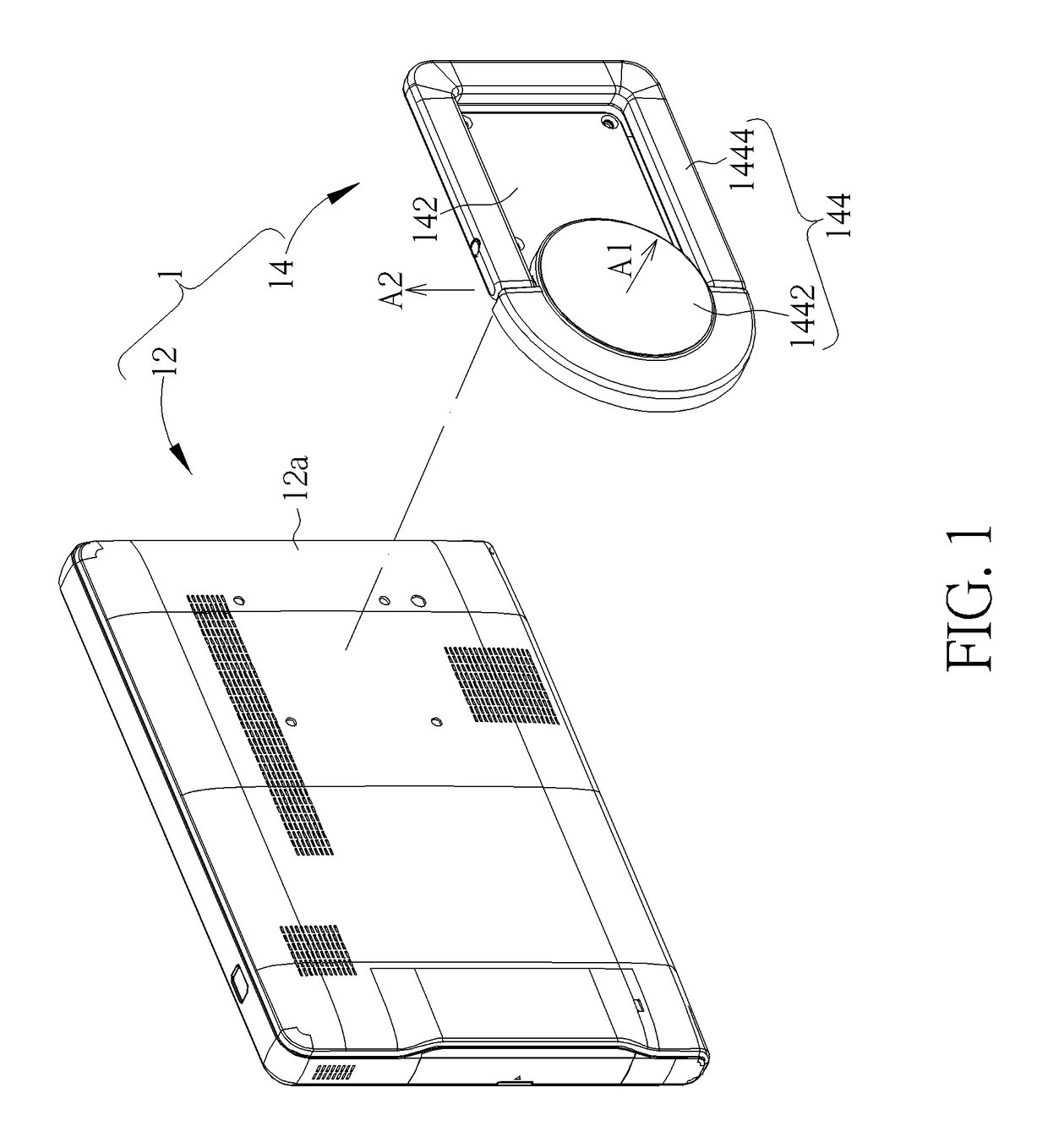
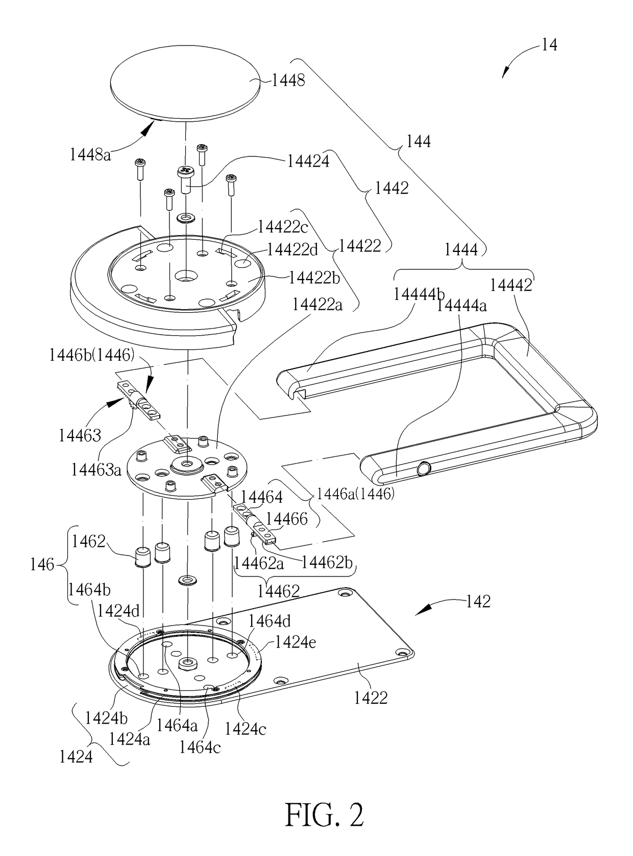
[0019]Please refer to FIG. 1, which is an assembly diagram of a display 1 with a supporting mechanism of an embodiment according to the invention. The display 1 includes a display module 12 and a supporting device 14. The supporting device 14 functions as the supporting mechanism of the display 1 for supporting the display module 12. The supporting device 14 includes a base 142 and a rotatable support 144. The rotatable support 144 is pivotally connected to the base 142. The base 142 is connected to a back cover 12a of the display module 12. Thereby, a user can manipulate the rotatable support 144 so as to support the display module 12, for example but not limited to, on a desktop or carry or hold the display module 12. Please also refer to FIG. 2. FIG. 2 is an exploded view of the supporting device 14. The rotatable support 144 includes a rotation member 1442, a handle 1444, and a connection member 1446. The rotation member 1442 is pivotally connected to the base 142. The handle 14...


PUM


Abstract

A display with a supporting mechanism includes a display module and a supporting device connecting the display module. The supporting device includes a base and a rotatable support. The base is used for fixing the display module and includes a first constraint structure. The rotatable support includes a rotation member pivotally connected to the base, a connection member, and a handle pivotally connected to the rotation member through the connection member. The connection member includes a second constraint structure engaged with or disengaged from the first constraint structure. Therein, when the rotation member is located at a position relative to the base, the first and second constraint structures are engaged with each and thus prevent the handle from rotating relative to the rotation member through the connection member, so that a user can carry the display module by gripping the handle with a hand.

Description

BACKGROUND OF THE INVENTION[0001]1. Field of the Invention[0002]The invention relates to a display, and especially relates to a display capable of being carried with a supporting device.[0003]2. Description of the Prior Art[0004]Currently, tablet devices are used widely. For satisfaction of different usage environments, accessories for convenience of users to use tablet devices are available on the market, such as supporting devices, protection covers and so on for the tablet devices. Conventional supporting devices for tablet devices are usually used independently or in coordination with a protection cover. For the above both cases, the supporting devices are usually designed to support the tablet devices on a plane such as a desktop. For the case that the supporting device is used independently, the supporting device needs to be stored when not in use, which causes the user inconvenience to a certain extent. When the tablet device needs to be transferred to another place, the user...

Claims


Application Information

Patent Timeline
Patent Type & Authority Patents(United States)
IPC IPC(8): F16M13/08F16M11/04F16M13/00F16M13/02F16B1/00
CPCF16M13/02F16M11/041F16M13/005F16B2001/0035F16M2200/021F16M2200/024F16M11/08F16M11/2021F16M13/022F16M13/04F16B2200/83F16M13/00
Inventor CHEN, CHIH-HUNGYEH, CHING-LINLING, KUO-WEI
Owner QISDA SUZHOU
Why Eureka
Try Eureka