
Robot control device and robot system
A control device and robot technology, which is applied in the directions of manipulators and manufacturing tools, etc., can solve the problems such as the expansion of the cable extension area and the increase of the occupation area of the robot system.
Patent Information
- Authority / Receiving Office
- CN · China
- Patent Type
- Patents(China)
- Current Assignee / Owner
- Publication Date
- 2009-07-29
- Estimated Expiration
- Not applicable · inactive patent
Smart Images
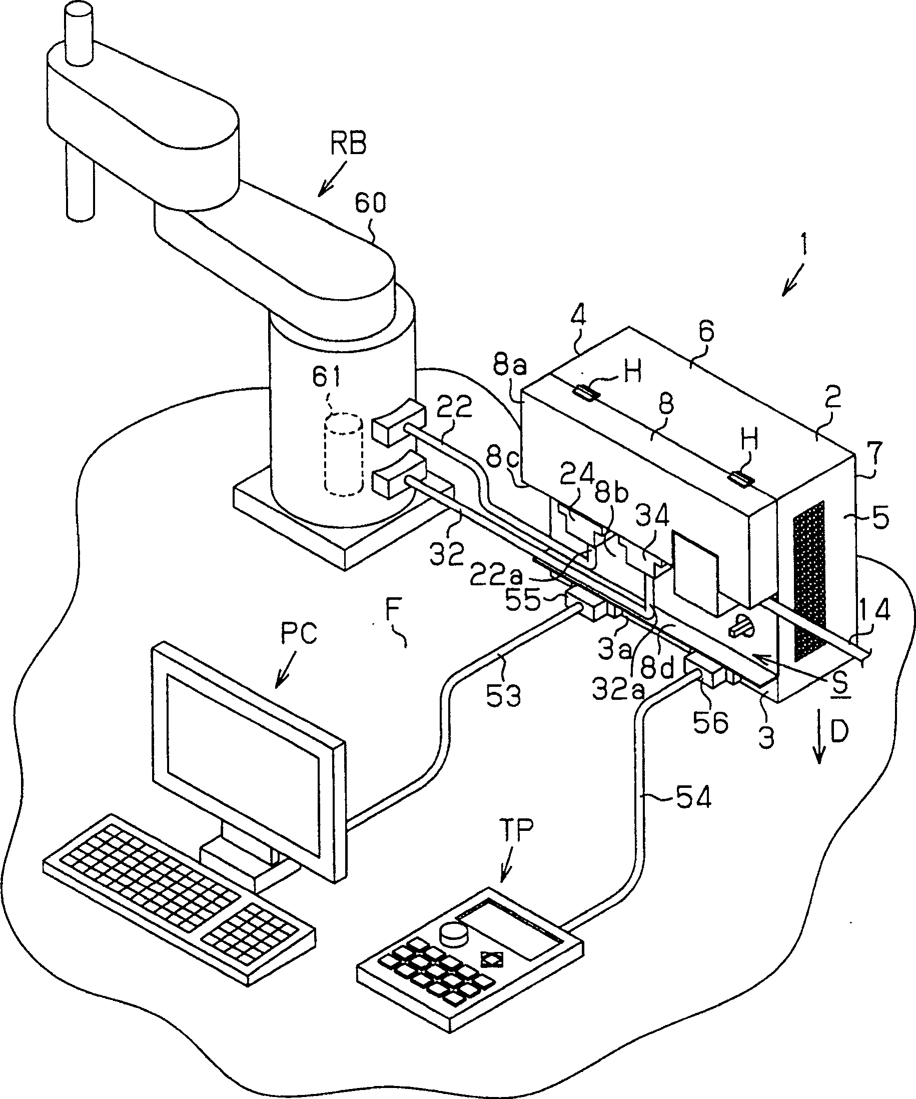
Figure 1 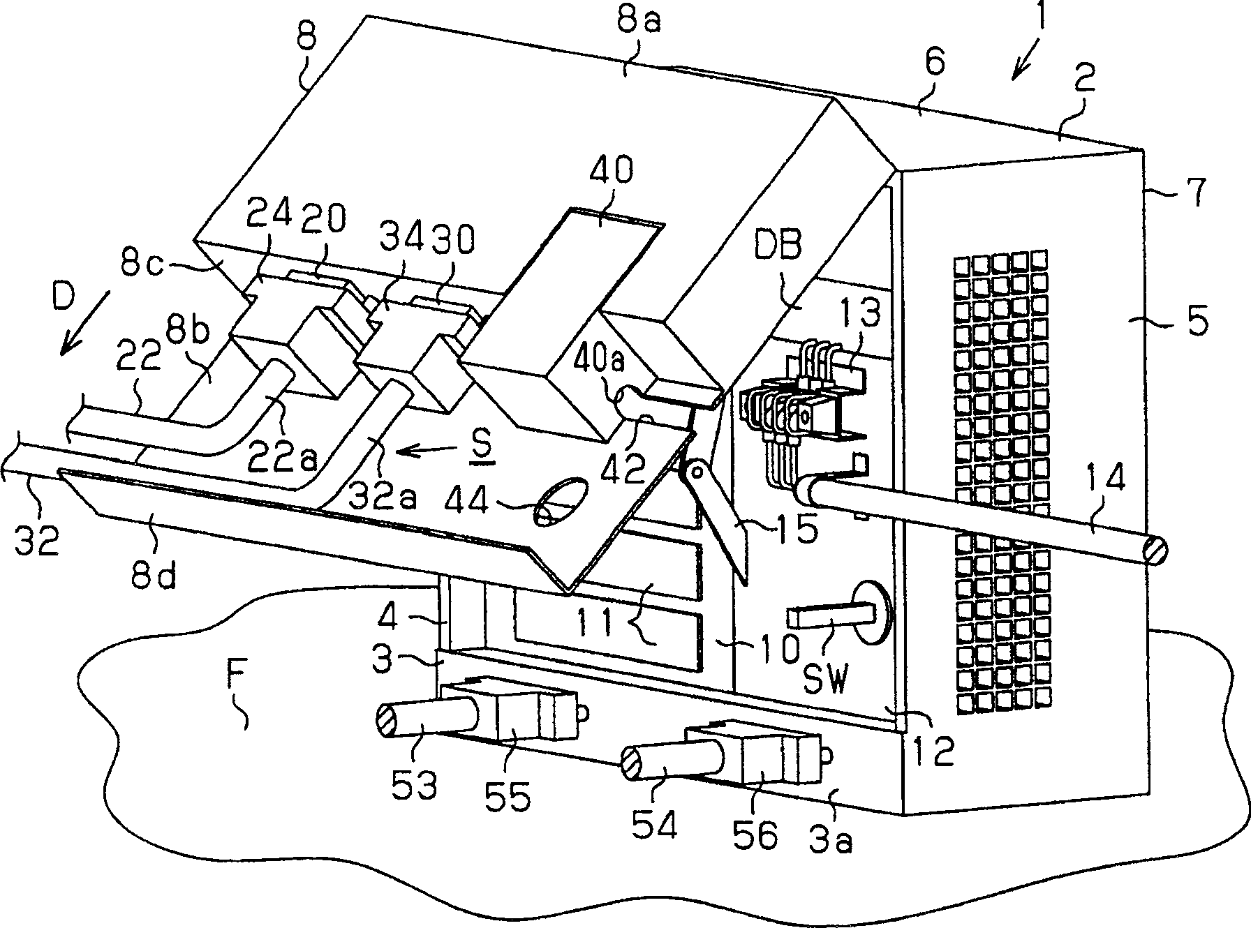
Figure 2 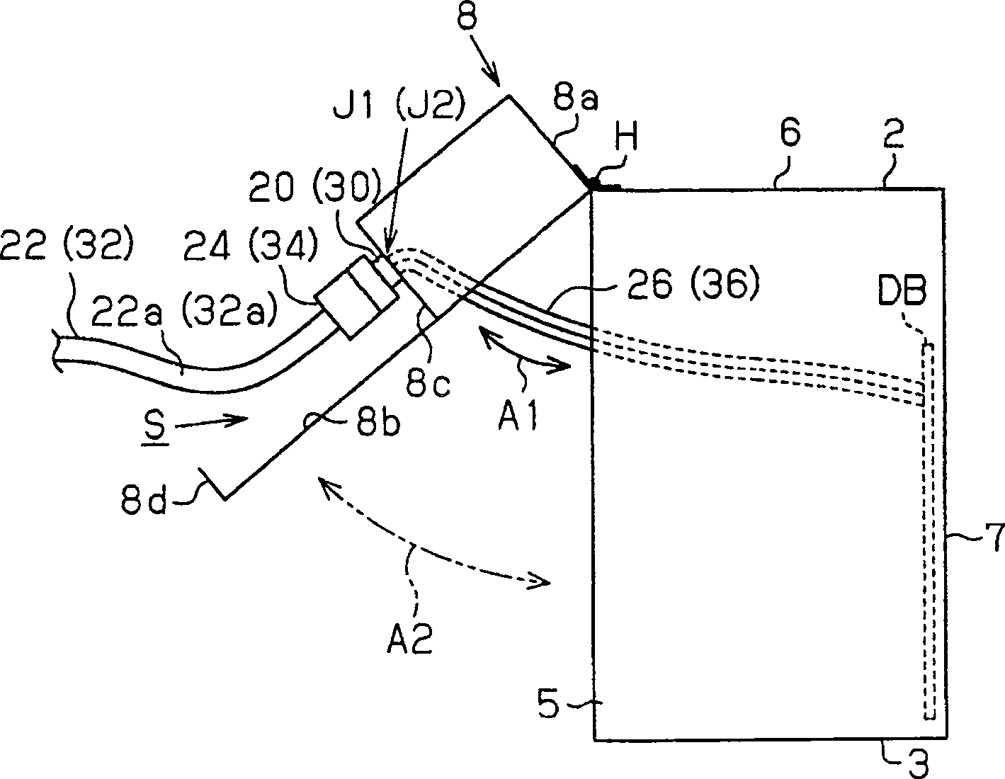
Figure 3
Abstract
Description
technical field
[0001] The invention relates to a robot control device and a robot system. Background technique
[0002] Generally, an industrial robot system has a robot control device connected to the industrial robot through a power cable or a signal cable. The industrial robots disclosed in JP-A-2001-67110 and JP-A-2000-66706 receive a signal output from a robot control device and perform processing operations corresponding to the signal.
[0003] In recent years, from the viewpoint of saving space in production equipment, reduction in the occupied space of robot systems has been strongly desired. However, as the number of joints of an industrial robot such as a horizontal multi-joint or a vertical multi-joint increases, the number of actuators for driving the joints also increases. As a result, the diameter of the cable for connecting the actuator to the robot controller becomes thicker.
[0004] When pulling out the cable from the robot controller while drawing it i...
Examples
Embodiment Construction
[0017] Below, follow Figure 1 ~ Figure 3 An embodiment in which the present invention is embodied will be described.
[0018] Such as figure 1 As shown, the robot system has an industrial robot RB and a controller 1 as a robot controller for driving the robot RB. The industrial robot RB includes a four-axis control type horizontal multi-joint robot arm 60 and a motor 61 as an actuator for driving the robot arm 60 .
[0019] The controller 1 has a rectangular parallelepiped housing 2 installed on the installation surface F. As shown in FIG. The box body 2 has: a base 3 disposed on the installation surface F, a left plate 4 disposed on the left end of the base 3, a right plate 5 disposed on the right end of the base 3, a left plate 4 and a right plate The top plate 6 of 5 upper ends. The box body 2 also has: a back panel 7 closing the rear opening of the space surrounded by the base 3, the left panel 4, the right panel 5 and the top panel 6, and an opening and closing contr...