
Ultraviolet lamp ionizing device
An ultraviolet lamp and vacuum ultraviolet lamp technology, applied in the field of mass spectrometry ionization sources, can solve the problems of difficulty in manufacturing and manufacturing cost of light sources, inability to ionize, difficult to apply and popularize, etc., and achieves wide working pressure range, low detection line, and wide range of samples to be tested. Effect
Patent Information
- Authority / Receiving Office
- CN · China
- Patent Type
- Applications(China)
- Current Assignee / Owner
- Publication Date
- 2012-05-30
- Estimated Expiration
- Not applicable · inactive patent
Smart Images
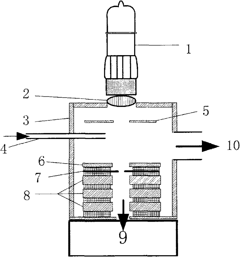
Figure 1 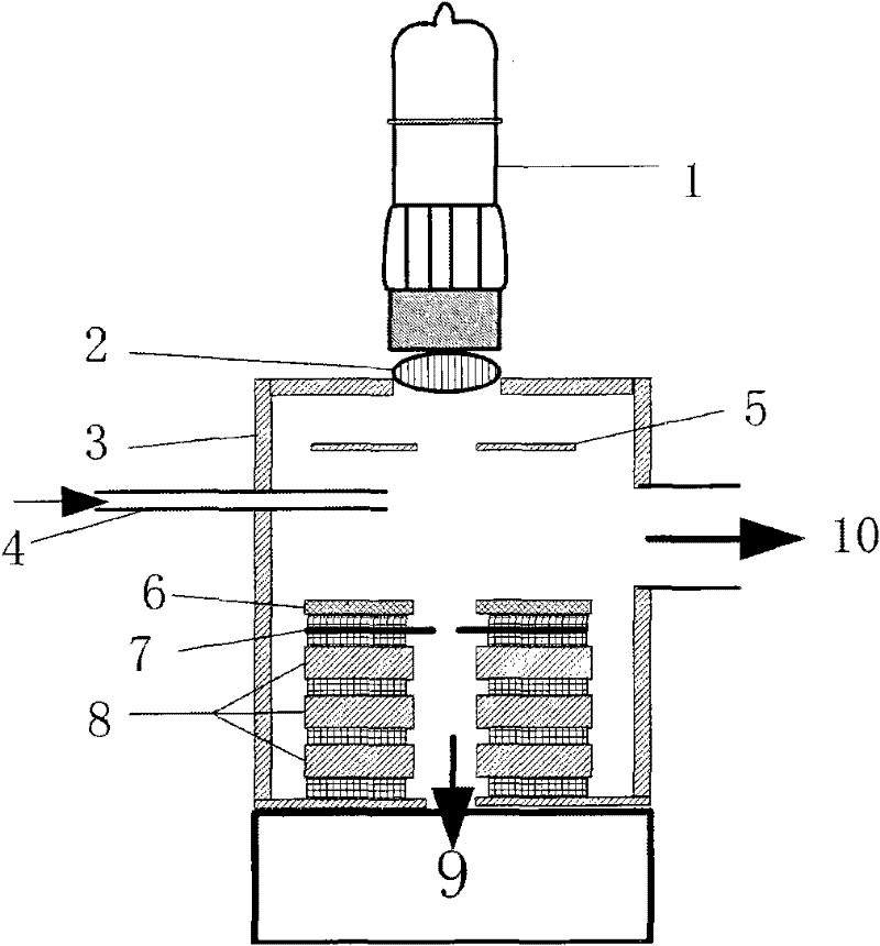
Figure 2
Abstract
Description
technical field
[0001] The invention relates to a mass spectrometer ionization source, which reduces the electron work function by using low electron work function materials, simultaneously uses a high-power ultraviolet light source and an optical focusing lens, and uses a magnetic field to enhance electron collision efficiency, thereby improving photoelectron generation efficiency; The technology has the advantages of low power consumption and resistance to oxidative gases, and is an alternative ionization source for electron impact ionization sources. Background technique
[0002] Electron impact ionization (EI) source is the most widely used ionization source in mass spectrometry because of its simplicity and practicality, as well as its rich spectral library. Its basic structure uses a pressurized hot wire as the electron source, and the accelerated electrons ionize neutral molecules in the ionization chamber. However, there are drawbacks to the design of the hot filame...
Examples
Embodiment Construction
[0024] Such as figure 1 As shown, a vacuum ultraviolet lamp ionization device includes an ionization chamber 3, an ultraviolet lamp 1 as a light source is installed above the ionization chamber 3, and a quartz lens 2 is arranged at 1-4 mm below the ultraviolet lamp 1,
[0025] A repelling electrode 5 is arranged at 4 mm directly below the quartz lens 2, and the repelling electrode is a metal disc with a hole in the middle, the aperture is 8 mm, and is coaxial with the quartz lens 2;
[0026] A focus ring 6 is provided at a distance of 10 mm directly below the repulsion electrode 5, the focus ring 6 is a magnetic material with a hole in the middle, the aperture is 8 mm, and is coaxial with the repulsion electrode 5;
[0027] A small hole plate 7 is provided at 4 mm directly below the focus ring 6, the small hole plate 7 is a circular plate with a hole in the middle, the aperture is 1 mm, and is coaxial with the repelling electrode 5;
[0028] Three coaxial lenses 8 are arrange...