
Novel rotary sealing structure for rotary shaft
A technology of rotating seals and rotating shafts, which is applied in the direction of engine seals, engine components, mechanical equipment, etc., and can solve the problems of cumbersome and laborious steps and easy wear of rotating seal rings
Patent Information
- Authority / Receiving Office
- CN · China
- Patent Type
- Patents(China)
- Current Assignee / Owner
- Publication Date
- 2014-08-13
Smart Images
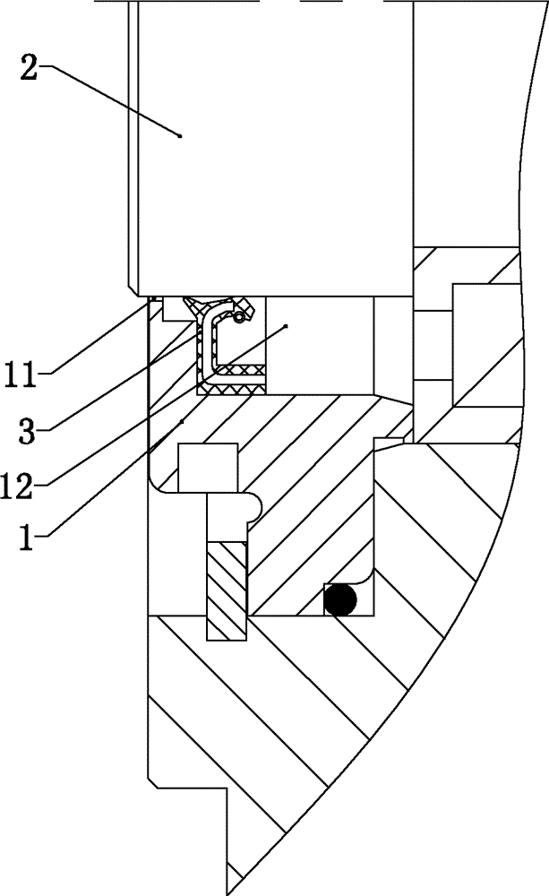
Figure 1 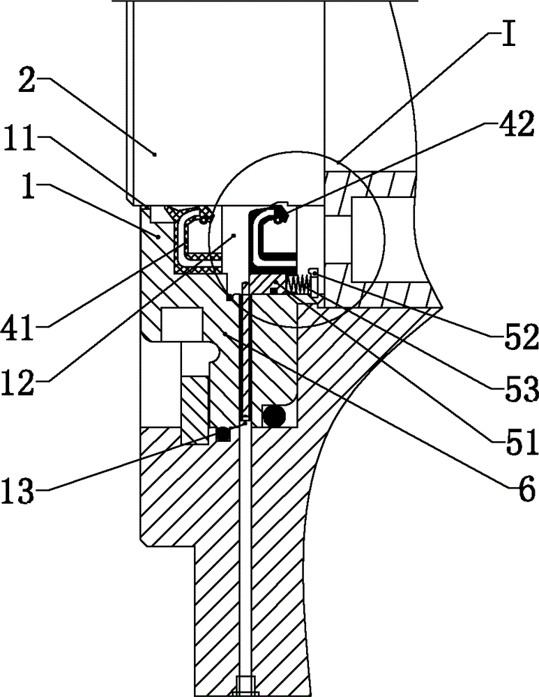
Figure 2 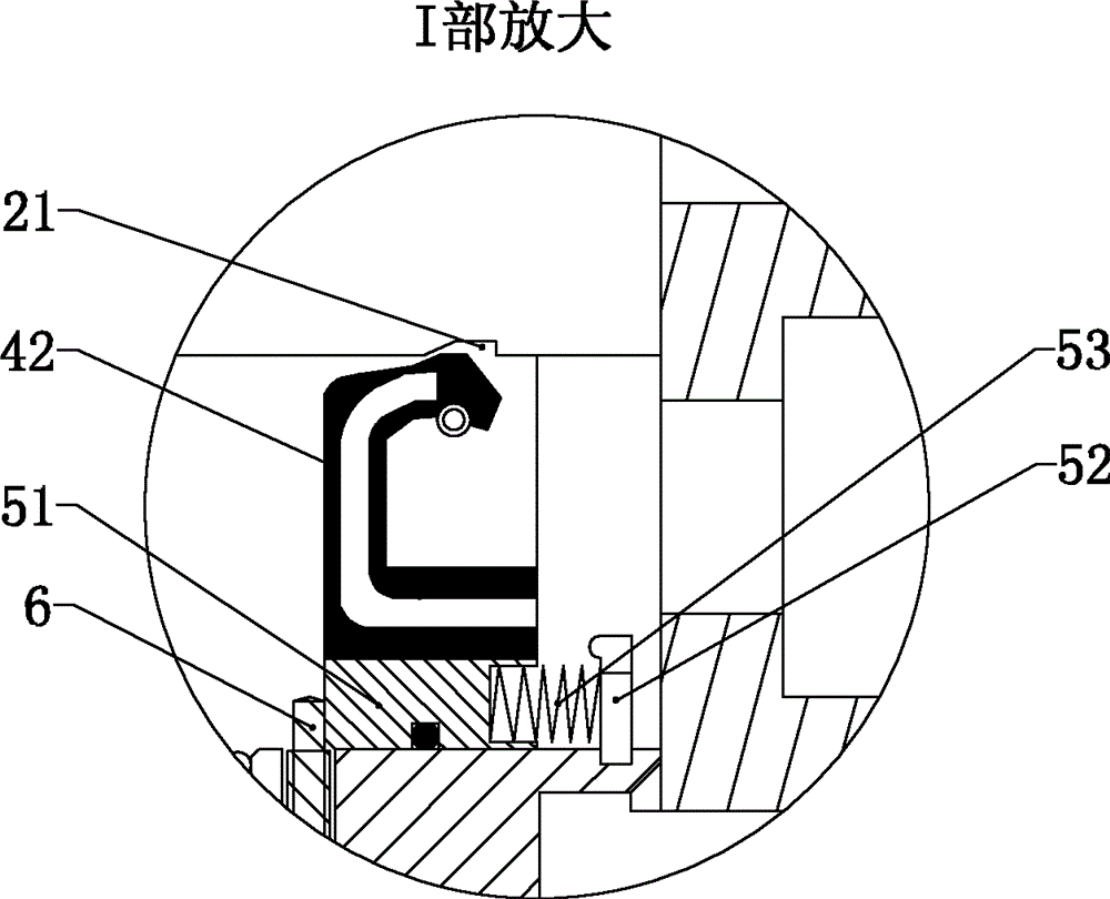
Figure 3
Abstract
Description
technical field
[0001] The invention relates to a rotary shaft sealing structure, in particular to a rotary shaft rotary sealing structure capable of extending the interval for replacing a rotary sealing ring by at least one time. Background technique
[0002] Existing hydraulic pumps, motors, gearboxes, motors, engines, propeller shafts and other equipment that have rotating main shafts and need to be sealed are generally equipped with such figure 1 The rotary shaft rotary seal structure shown. The rotary shaft rotary seal structure usually includes an end cover 1, a rotary shaft 2 and a rotary seal ring 3. The end cover 1 is provided with a rotary shaft installation hole 11 and a rotary seal ring installation groove 12. The shaft mounting hole 11 , while the rotary seal ring 3 is sleeved on the end of the rotary shaft 2 and placed in the rotary seal ring installation groove 12 . However, since there is only one rotating sealing ring 3, and the rotating sealing ring is mo...
Examples
Embodiment 1
[0019] Such as figure 2 and image 3 As shown, the rotating shaft rotating sealing structure described in this embodiment includes an end cover 1, a rotating shaft 2, a main rotating sealing ring 41, a backup rotating sealing ring 42, a thrust generating mechanism and a positioning mechanism.
[0020] The end of the rotating shaft 2 is passed through the rotating shaft installation hole 11 of the end cover 1 , and the main rotating seal ring 41 is sleeved on the end of the rotating shaft 2 and placed in the rotating sealing ring installation groove 12 of the end cover. The spare rotary sealing ring 42 is vacantly sleeved on the end of the rotating shaft 1, and the side wall of the end of the rotating shaft 2 is provided with a hole corresponding to the set position of the spare rotating sealing ring 42 to avoid contact between the spare rotating sealing ring and the rotating shaft. Annular groove 21.
[0021] The thrust generating mechanism is made up of a slide block 51 , ...
Embodiment 2
[0025] Such as Figure 4 and Figure 5 As shown, in this embodiment, on the basis of Embodiment 1, a spare rotary sealing ring 42 is added, and a thrust generating mechanism and a positioning mechanism are correspondingly added.
[0026] As mentioned above, when both the main rotary seal ring and the first backup rotary seal ring lose their sealing effect due to wear and tear, the rotary seal structure can resume its sealing effect by unscrewing the second screw. Therefore, compared with the existing rotary sealing structure, the rotary sealing structure of this embodiment prolongs the replacement interval of the sealing ring twice.