
A key detection circuit and detection method
A detection circuit and detection method technology, which is applied in the key field, can solve the problems of complex circuit design, poor practicability, and high production cost, and achieve the effects of reducing production cost, strong applicability, and high reliability
Patent Information
- Authority / Receiving Office
- CN · China
- Patent Type
- Patents(China)
- Current Assignee / Owner
- Publication Date
- 2016-03-09
Smart Images
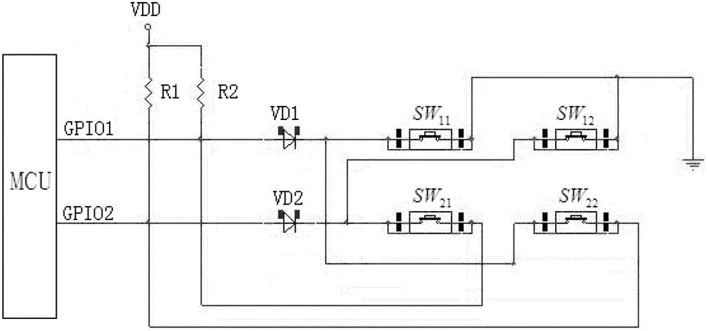
Figure 1 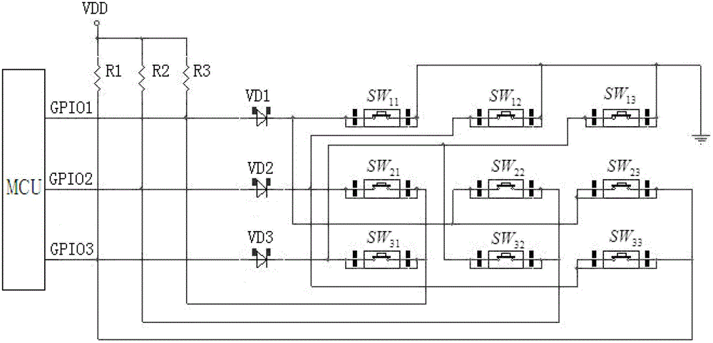
Figure 2
Abstract
Description
technical field
[0001] The invention relates to key technology, in particular to a key detection circuit. Background technique
[0002] When a system has fewer general-purpose input / output interfaces (GPIO for short), it usually can only support fewer buttons, and the number of GPIOs is the same as the number of detection buttons. For example, when the number of GPIOs is 3, the number of buttons is also 3, so it is necessary to add identifiable buttons without changing the number of GPIOs, which can only be realized by adding additional devices, which makes the circuit design more complicated. Simultaneously production cost is also high, and practicality is lower. The existing matrix scanning circuit used in the market can realize the real-time detection of 9 buttons through 6 GPIOs, but this still requires a large number of GPIOs to realize the real-time scanning of the buttons, the practicability is still not strong, and the production cost is high.
[0003] Therefore, i...
Examples
Embodiment 1
[0046] figure 1 It shows a circuit diagram in which the CPU sets two GPIO interfaces to detect 4 keys. Such as figure 1 as shown,
[0047] The button detection circuit includes the central processing unit MCU, 4 buttons SW 11 、SW 12 、SW 21 、SW 22 and power supply, the central processing unit MCU is set with GPIO 1 , GPIO 2 Two GPIO interfaces, GPIO 1 , GPIO 2 respectively through pull-up resistors R 1 , R 2 Connect to power supply. Among them GPIO 1 , GPIO 2 Constitute 4 detection circuits.
[0048] When GPIO 1 , GPIO 2 When both are input interfaces: GPIO 1 , GPIO 2 Respectively via the button SW 11 、SW 12 Grounded to form 2 detection lines;
[0049] When GPIO 1 For the output interface, GPIO 2 When it is an input interface: GPIO 2 by SW 21 with GPIO 1 Composition detection SW 21 detection line;
[0050] When GPIO 2 For the output interface, GPIO 1 When it is an input interface: GPIO 1 by SW 22 with GPIO 2 Composition detection SW 22 detectio...
Embodiment 2
[0059] figure 2 It shows a circuit diagram in which the central processing unit sets three GPIO interfaces to realize detection of 9 keys. Such as figure 2 As shown, the button detection circuit includes a central processing unit MCU, 9 buttons and a power supply, and the central processing unit MCU is provided with GPIO 1 , GPIO 2 , GPIO 3 Three GPIO interfaces, GPIO 1 , GPIO 2 , GPIO 3 respectively through pull-up resistors R 1 , R 2 , R 3 Connect to power supply. Among them GPIO 1 , GPIO 2 , GPIO 3 Three GPIO interfaces form nine detection circuits.
[0060] When all three GPIOs are input interfaces: GPIO 1 , GPIO 2 , GPIO 3 Respectively via the button SW 11 、SW 12 、SW 13 Grounded to form 3 detection lines;
[0061] When GPIO 1 For the output interface, GPIO 2 , GPIO 3 When it is an input interface: GPIO 2 by SW 21 with GPIO 1 Composition detection SW 21 detection line; GPIO 3 by SW 31 with GPIO 1 Composition detection SW 31 detection line; ...