
High precision on-chip clock oscillator based on cmos technology
A clock oscillator, high-precision technology, applied in the electrical field, can solve the problems of high power consumption, high cost, low frequency temperature and voltage coefficient of MEMS implementation, and achieve good temperature and process stability, good noise performance, Simple circuit effect
Patent Information
- Authority / Receiving Office
- CN · China
- Patent Type
- Patents(China)
- Current Assignee / Owner
- Publication Date
- 2016-01-20
Smart Images
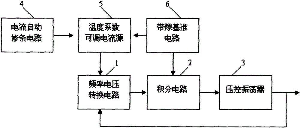
Figure 1 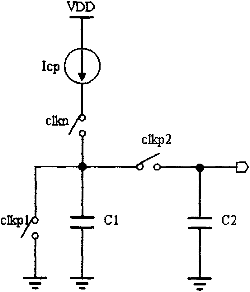
Figure 2 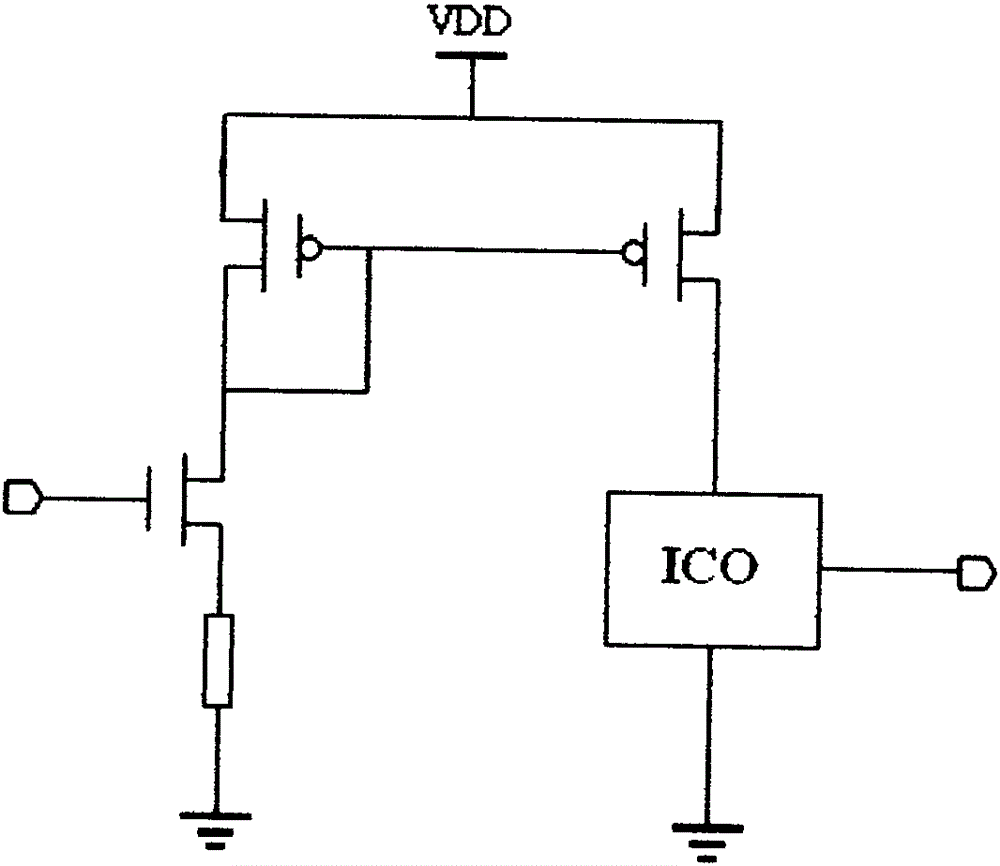
Figure 3
Abstract
Description
technical field
[0001] The invention relates to the field of electricity, in particular to a clock oscillation circuit, in particular to a high-precision on-chip clock oscillator based on CMOS technology. Background technique
[0002] In various electronic systems, a crystal oscillator (XTAL) is an essential clock reference signal. Widely used in computers, remote controls and automatic control circuits. It is mainly used in frequency generators in communication systems to generate clock signals for data processing equipment to maintain the synchronization of signal transmission. Although crystal oscillators can generate accurate clock signals, the clock signals generated by crystal oscillators have the disadvantages of high cost, high power consumption of the system, and the shortcomings of not being able to be integrated into the chip. There is no way to achieve low-cost, Requirements for low power consumption and miniaturization, especially in biomedical chips and IoT c...
Examples
Embodiment Construction
[0020] The present invention will be described in detail below with reference to the accompanying drawings and in combination with embodiments.
[0021] refer to figure 1 As shown, a high-precision on-chip clock oscillator based on CMOS technology includes a frequency-voltage conversion circuit 1, an integrating circuit 2, a voltage-controlled oscillator 3, an automatic current trimming circuit 4, a current source with adjustable temperature coefficient 5 and a Gap reference circuit 6, the frequency voltage conversion circuit 1, the integration circuit 2 and the voltage controlled oscillator 3 are sequentially connected to form a closed-loop structure; the frequency voltage conversion circuit 1 is connected to the temperature coefficient adjustable current source 5 , the current automatic trimming circuit 4 and the bandgap reference circuit 6 are connected to the temperature coefficient adjustable current source 5 respectively, and the bandgap reference circuit 6 is also conne...