

Distance-adjustable energy-saving daylighting roof
An adjustable and daylighting roof technology, which is applied to roofs, roofs using flat/curved panels, roofs, etc., can solve the problems of inaccurate installation of glass panels and inability to adjust distances, and achieve good flatness and precise installation.
Patent Information
- Authority / Receiving Office
- CN · China
- Current Assignee / Owner
- Publication Date
- 2013-09-18
- Estimated Expiration
- Not applicable · inactive patent
Smart Images
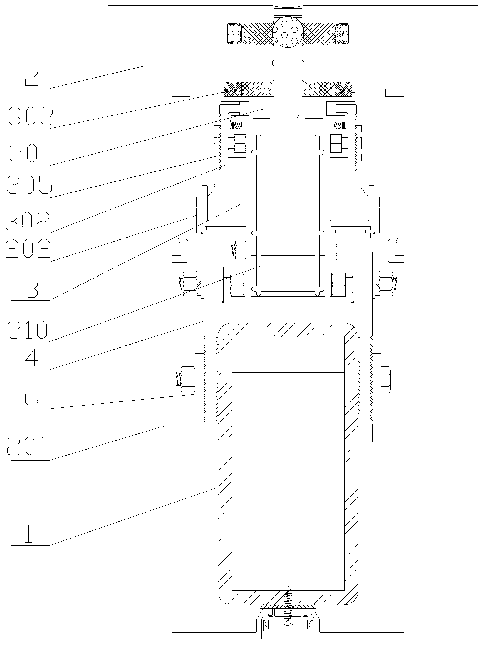
Figure 1 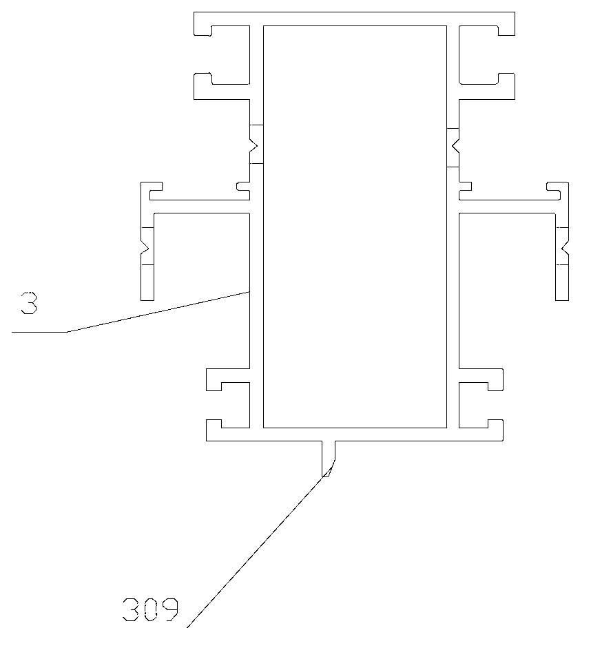
Figure 2 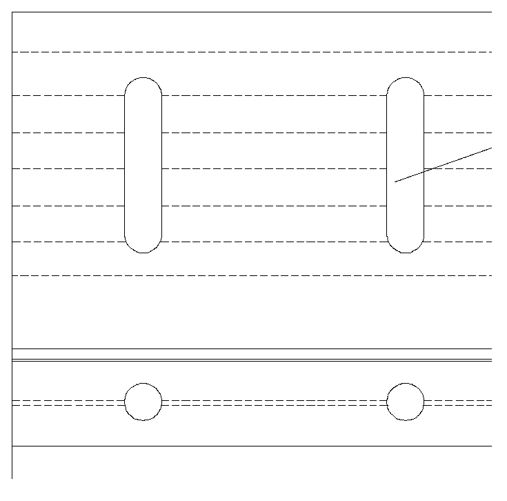
Figure 3
Abstract
Description
technical field
[0001] The invention relates to the technical field of construction engineering, in particular to an energy-saving lighting roof with an adjustable distance. Background technique
[0002] Energy-saving daylighting roofs are a new development trend in the industry. Green energy is obtained through solar panels installed on the outer surface and used for lighting and temperature control of the building itself, organically combining daylighting and energy saving. Energy-saving daylighting roofs, especially large super-high-rise energy-saving daylighting roofs, have relatively high top heights, relatively large wind loads, and require good permeability at the same time. The current conventional method is: use the steel structure as the skeleton, fix the columns with the steel structure framework, and then assemble glass plates and other components on the columns. Since the installation holes on the steel structure frame are facing the glass plate, it is difficul...
Examples
Embodiment Construction
[0024] The specific implementation manners of the present invention will be further described in detail below in conjunction with the accompanying drawings and embodiments. The following examples are used to illustrate the present invention, but are not intended to limit the scope of the present invention.
[0025] Such as Figure 1 to Figure 8 The distance-adjustable energy-saving daylighting roof shown includes: a steel structure frame 1 , a glass plate 2 , a column 3 and a column connector 4 . The glass plate 2 is fixed on the column 3 through the glass sub-frame 301 and the inner pressure plate 302 . The side of the steel frame 1, the side of the column 3 and the column connector 4 are all provided with installation holes, the axial direction of the installation hole is parallel to the plane of the glass plate 2, and the column connector 4 is connected to the steel plate through the bolts in the installation hole. The structural skeleton 1 is fixedly connected, and the c...