
Fluid-flow control device and shower head
A fluid flow control and shaft control technology, which is applied to spray devices, spray devices, etc., can solve the problems of complex device structure, large water inlet resistance, and large space occupation, and achieve the effect of simple operation and compact overall structure.
Patent Information
- Authority / Receiving Office
- CN · China
- Current Assignee / Owner
- Publication Date
- 2013-10-30
Smart Images
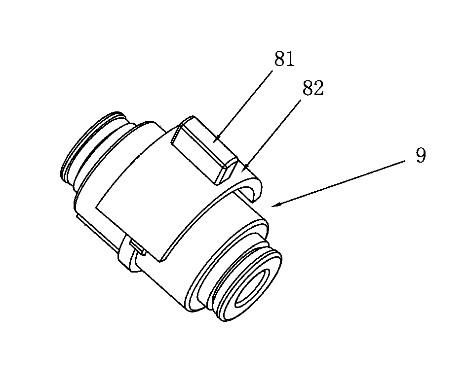
Figure 1 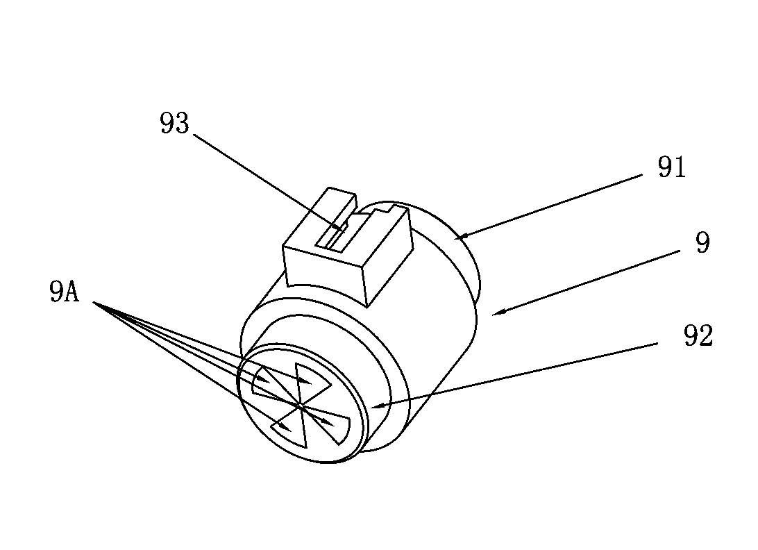
Figure 2 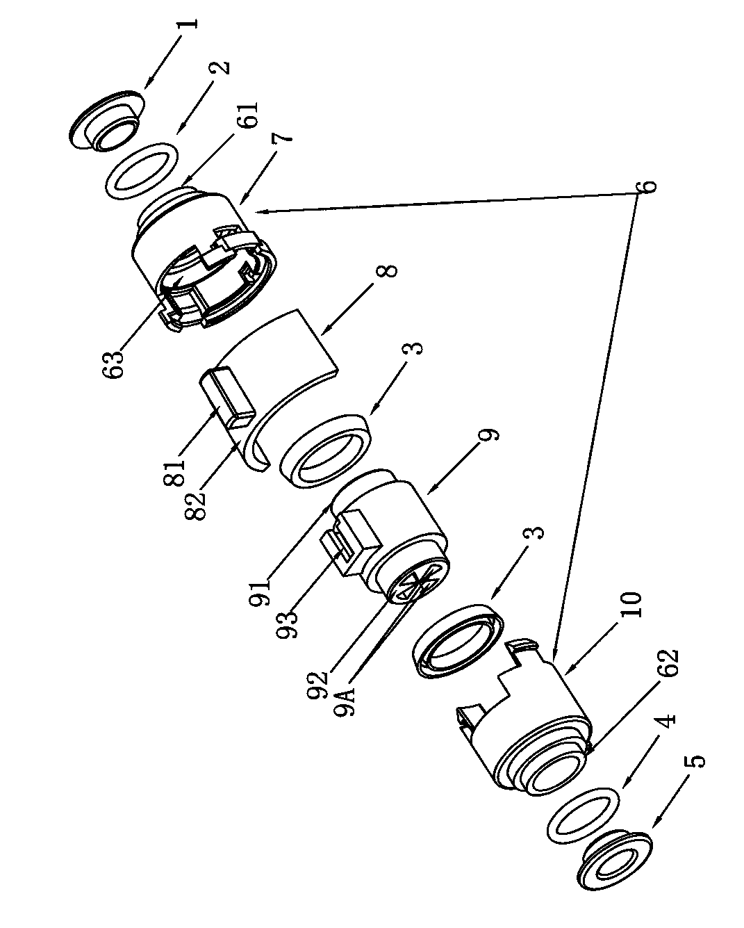
Figure 3
Abstract
Description
technical field
[0001] The invention relates to a fluid flow control device and a shower provided with the control device. Background technique
[0002] At present, when the fluid flow control device in the prior art is controlled by a push button, the water inlet resistance is large, and the force of the control push button is also large; when the button is used for control, only the size of the water can be adjusted, and more can not be achieved. Level regulation flow. And the device structure that the prior art adopts is complex, takes up a large space, and is inconvenient to operate. Contents of the invention
[0003] In order to solve the technical problems in the prior art, the present invention provides a fluid flow control device with convenient flow control and stable function, and a shower comprising the flow control device.
[0004] The present invention solves the above-mentioned technical problems, and the adopted technical solution is: provide a fluid flow ...
Examples
Embodiment Construction
[0035] In order to make the technical problems, technical solutions and beneficial effects to be solved by the present invention clearer and clearer, the present invention will be further described in detail below in conjunction with the accompanying drawings and embodiments. It should be understood that the specific embodiments described here are only used to explain the present invention, not to limit the present invention.
[0036] like figure 1 , figure 2 , image 3 , Figure 4 As shown, the fluid flow control device of the present invention includes a box structure 6 and a control shaft 9 . The inside of the box structure 6 is provided with a cavity, and its first end surface 61 is in an open state, and its second end surface 62 is provided with a first water passage 10A. The wall surface of the box structure 6 is provided with a slot 63 communicating with the inside and outside. The inside of the control shaft 9 is provided with a buffer chamber 90 , which is arran...