
Three-fork connecting rod self-adjusting coil spreader
A self-adjusting, trident technology, applied in the field of spreaders, can solve problems such as limited weight of hoisted objects, potential safety hazards, and limited manpower, and achieve the effects of improving work efficiency and safety factor, reducing labor intensity, and improving the working environment
Patent Information
- Authority / Receiving Office
- CN · China
- Current Assignee / Owner
- Publication Date
- 2016-01-27
Smart Images
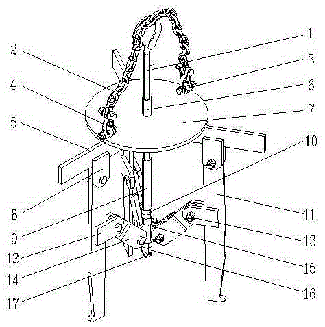
Figure 1 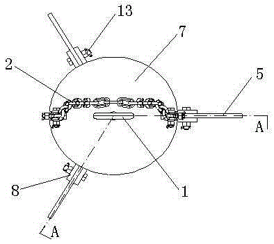
Figure 2 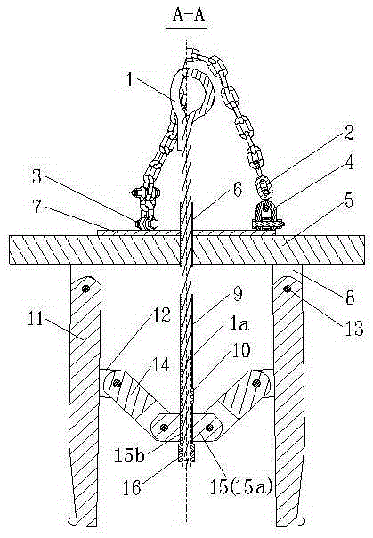
Figure 3
Abstract
Description
technical field
[0001] The invention relates to a sling for hoisting a coiled product with internal voids, in particular to a self-adjusting coiled sling with a three-fork link. Background technique
[0002] With the development of modern economy and technology, large single heavy coils are gradually replacing straight round steel and widely used in transportation, equipment manufacturing, electronics industry, hardware and home appliances, light steel structure, construction and other industries. In order to reduce the development requirements of energy consumption, high-strength steel is gradually replacing medium-strength steel. Most high-strength steels require heat treatment (eg: spheroidizing annealing, stress relief annealing, etc.) before cold working (eg: drawing, upsetting, turning, etc.). At present, domestic coil heat treatment generally adopts well furnace , due to the special structure of the pit furnace, the weight of the coil (generally ≥ 2 tons / reel), and t...
Examples
Embodiment
[0014] Example: A preferred embodiment of the present invention is as follows, the self-adjusting coil spreader of the tripod link, such as figure 1 , figure 2 and image 3 , the hanging lugs 3 are symmetrically welded on the top of the hanging plate 7, the lifting chain 2 is connected to the hanging lugs 3 through two sets of D-shaped shackles 4, and the first fixed connection arm 8 on the hanging plate 7 and the support arm 5 is formed. On the balance structure, the three suspension arms 11 are connected by bolts 13, and the circular screw rod 1 passes through the guide tube 6 on the hanging plate 7 at the center position of the balance structure. like Figure 4 , the screw body of the ring screw 1 is equipped with a movable limit sleeve 9 and a trident connecting arm sleeve 15. The trident connecting arm sleeve 15 is composed of three connecting lugs 15a uniformly welded on the outside of the sleeve 15b. The movable limit sleeve 9 Two adjusting nuts 10 are installed w...