
An ultrasonic paper thickness measuring device
An ultrasonic and paper technology, applied in the direction of measuring devices, using ultrasonic/sonic/infrasonic waves, instruments, etc., can solve the problems of high surface precision around the paper shaft, unfavorable industrial promotion and use, and inability to exert precision, so as to reduce disadvantages Effects of impact, lower center of gravity, and low production cost
Patent Information
- Authority / Receiving Office
- CN · China
- Patent Type
- Patents(China)
- Current Assignee / Owner
- Publication Date
- 2017-01-25
Smart Images
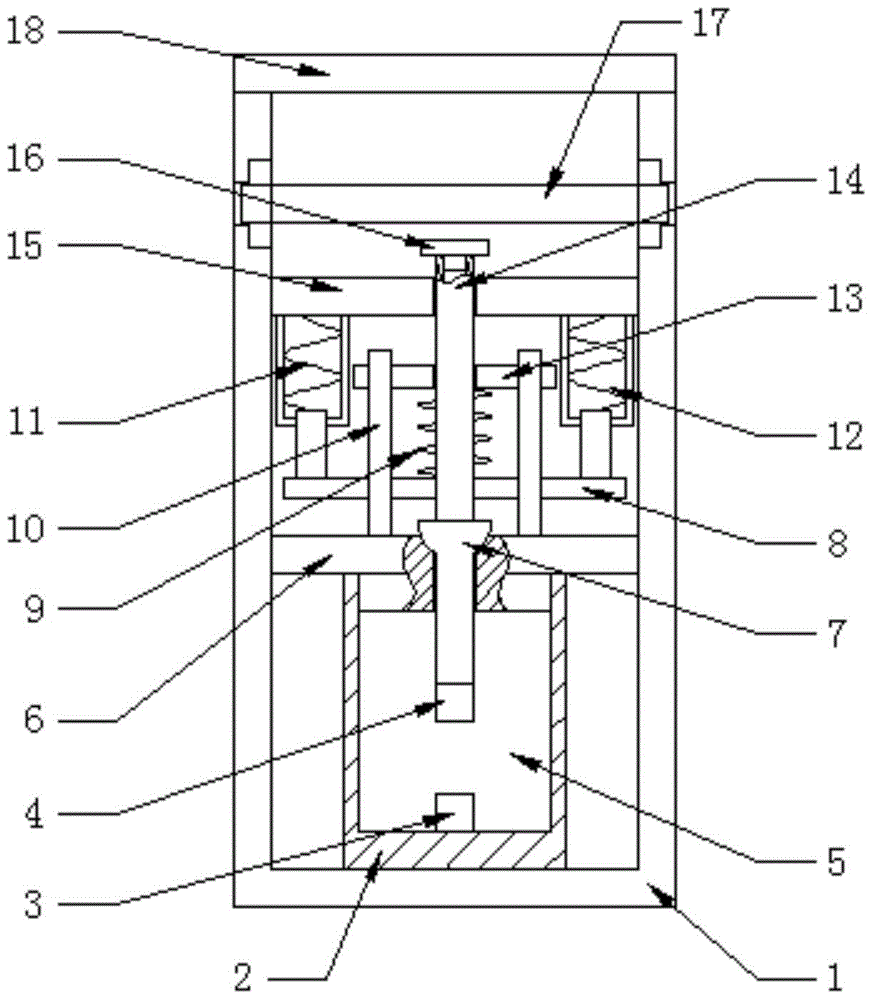
Figure 1 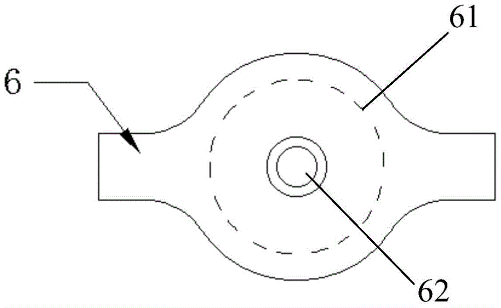
Figure 2 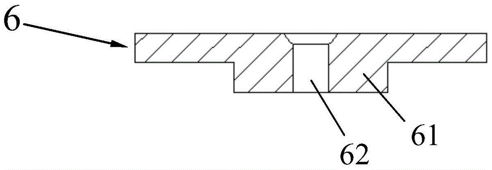
Figure 3
Abstract
Description
technical field
[0001] The invention relates to ultrasonic distance measuring technology, in particular to an ultrasonic thickness measuring device for measuring the thickness of paper products. Background technique
[0002] Paper is an indispensable consumable in life and work, and its quality inspection has always been a relatively important issue. Because the thickness of the paper is generally thin, and some characteristics of the paper, such as uneven fiber distribution, many gaps, easy to be deformed by external force, and cannot be immersed in liquid, etc., the measurement work is very difficult. For thickness measurement, traditional measurement methods are divided into contact measurement and non-contact measurement. The current paper thickness detection generally adopts a non-contact method. Non-contact methods are divided into ultrasonic measurement principle thickness measurement, eddy current effect principle thickness measurement and Hall principle thickness ...
Examples
Embodiment Construction
[0027] The method of the present invention will be further described below in conjunction with the embodiments and accompanying drawings.
[0028] Ultrasonic paper thickness measuring device designed by the present invention (abbreviation thickness measuring device, see Figure 1-7 ), including bracket 1, tank body 2, upper ultrasonic probe 3, lower ultrasonic probe 4, tank upper cover 6, hemispherical valve 7, movable pin 8, spring 9, bracket with chute 10, left electromagnet 11, right electromagnetic Iron 12, limit pin 13, cylindrical tube 14, upper cover 15, measuring end face 16, winding paper shaft 17 and upper bracket 18.
[0029] The tank body 2 is placed on the bracket 1; the upper ultrasonic probe 3 is installed at the bottom of the tank body 2; the liquid 5 is housed inside the tank body 2; There is a spherical hole 62 in the middle of 61 that matches the hemispherical valve 7, and the tank upper cover 6 and the tank body 2 are connected together through the round p...