
Fallopian tube recanalization body position rack
A technology for fallopian tubes and body positions, which is applied in patient positioning for diagnosis, medical science, surgery, etc. It can solve problems such as inability to adjust, inability to adjust the size, and no good solution, and achieve the effect of convenient adjustment
Patent Information
- Authority / Receiving Office
- CN · China
- Patent Type
- Applications(China)
- Current Assignee / Owner
- Publication Date
- 2014-07-30
- Estimated Expiration
- Not applicable · inactive patent
Smart Images
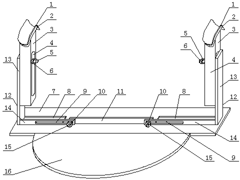
Figure 1 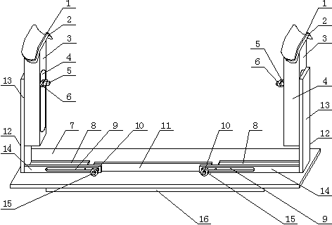
Figure 2 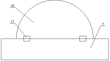
Figure 3
Abstract
Description
technical field
[0001] The invention relates to a medical auxiliary machine, in particular to a fallopian tube recanalization position stand. Background technique
[0002] The gynecological bed is essential in clinical obstetrics and gynecology. Interventional tubal recanalization is a minimally invasive diagnosis and treatment of tubal obstruction diseases under the guidance of X-rays and using catheter guide wire technology. safe and effective treatment. During the treatment process, patients need to use their lithotomy position to carry out interventional diagnosis and treatment under the guidance of X-rays. However, since ordinary catheter beds do not have lithotomy position stands, it is difficult for patients to take lithotomy positions for a long time. If a position stand is installed on the catheter bed, It will also affect the intraoperative operation and X-ray machine operation of other non-intervention patients in this position. In the prior art, most of the lit...
Examples
Embodiment Construction
[0021] Attached below figure 1 to attach Figure 6 The present invention is described further:
[0022] A fallopian tube recanalization position frame, comprising a base 7 and a popliteal fossa support device, the popliteal fossa support device comprising two popliteal fossa support plates 2, two vertical supports 3 and two horizontal supports 12, the popliteal fossa support plate 2 Fixed on the top of the vertical support 3, the vertical support 3 is movably arranged on the horizontal support 12, and can move up and down in the vertical direction; the base 7 is provided with two symmetrical chute 8, and the chute 8 is respectively placed There is a horizontal support 12, and a vertical plate 11 is arranged between the two chutes 8, and one end of the horizontal support 12 is movably arranged on the vertical plate 11, and can move left and right along the horizontal direction; the front end of the base 7 passes through the hinge 17 A pressing plate 16 is fixed.
[0023] In ...