
Self-switching voltage stabilizing circuit of power supply
A technology of power switching and voltage stabilizing circuits, applied in circuit devices, emergency power supply arrangements, electrical components, etc., can solve the problems of low heavy-load voltage, large light-load voltage, unstable output voltage, etc., to achieve high efficiency and flexible design Effect
Patent Information
- Authority / Receiving Office
- CN · China
- Patent Type
- Applications(China)
- Current Assignee / Owner
- Publication Date
- 2014-09-03
- Estimated Expiration
- Not applicable · inactive patent
Smart Images
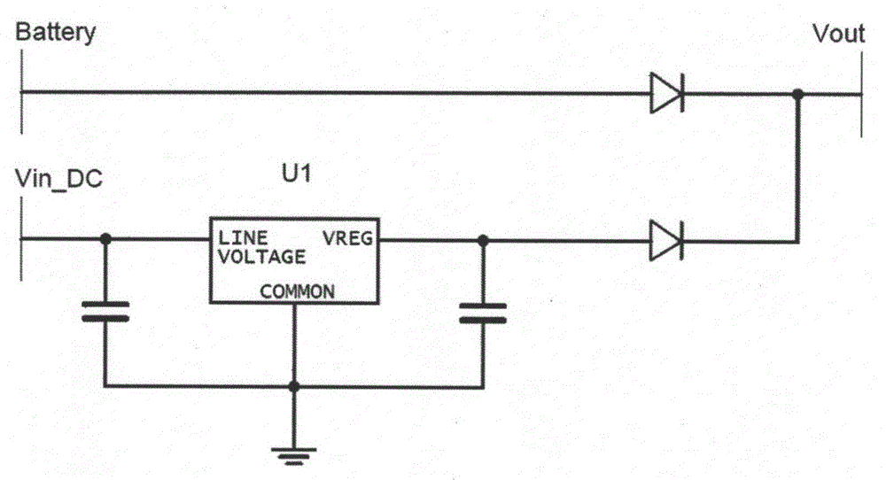
Figure 1 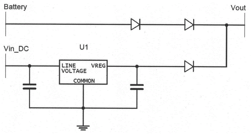
Figure 2 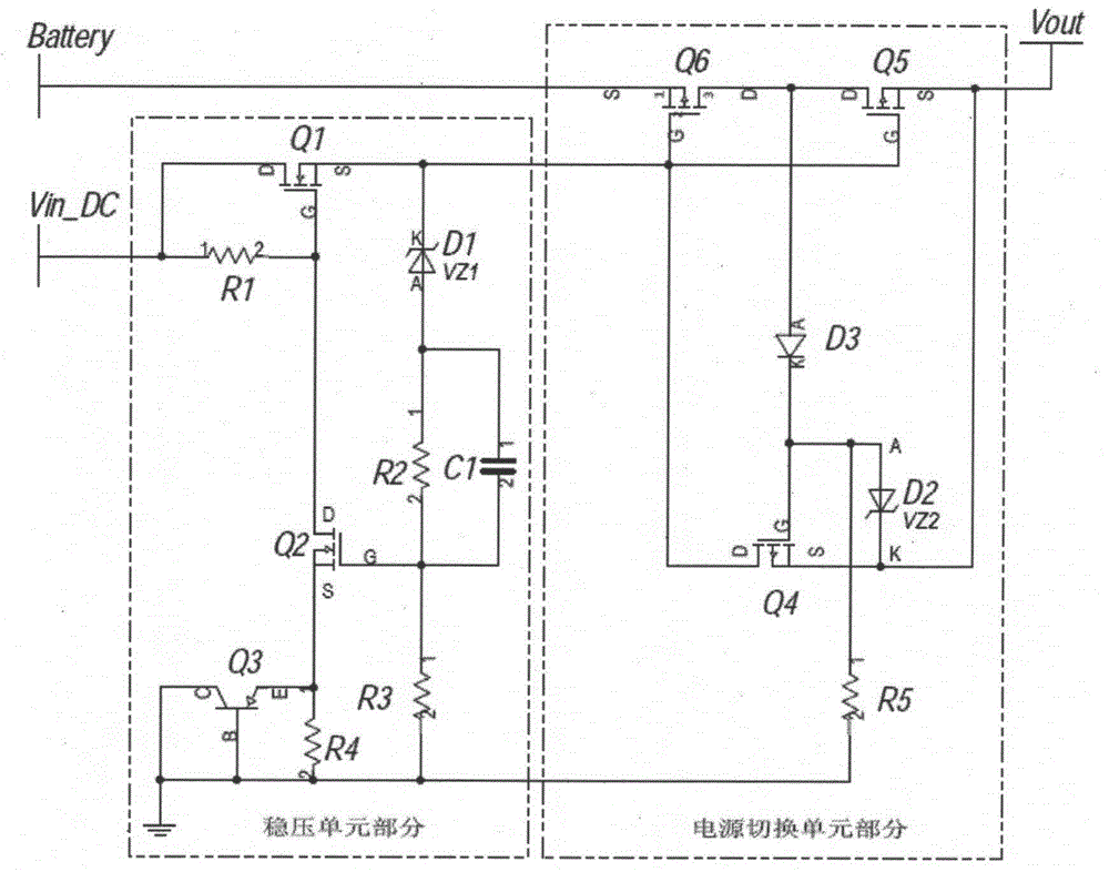
Figure 3
Abstract
Description
technical field
[0001] The invention relates to a voltage stabilizing circuit supporting automatic switching of external direct current and backup battery supply. Background technique
[0002] In the design of low-power instruments, 3.6V Li-SOCL2 disposable lithium batteries are often used as backup power for RTC, MCU or LCD and other low-power circuits after power failure. In the circuit design, it is necessary to design a switching circuit for the power supply selection after the external DC power supply is powered off or powered on. The conventional method is as follows: figure 1 As shown, the low-dropout linear regulator U1 and the diode switching method are used. The switching circuit adopts the diode isolation method. It must ensure that the external DC power supply voltage is greater than the battery voltage to ensure correct switching.
[0003] When the voltage stabilizing unit outputs 5V, the circuit can ensure accurate switching. However, as integrated circuits a...
Examples
Embodiment Construction
[0022] In order to make the present invention more comprehensible, preferred embodiments are described in detail below with accompanying drawings.
[0023] combine image 3 and Figure 5 Application description, a self-switching power supply voltage stabilizing circuit provided by the present invention is composed of a voltage stabilizing circuit unit and a switching unit. In the simulation example, the voltage DC INPUT input from the external power supply voltage input terminal Vin_DC is the external DC power input, and Rsoure is used to change the DC voltage of the external DC power input unit, which can output a DC voltage of 0-60V. SW1 is a switch, which is used to simulate the switch for controlling the external DC power supply. Rload1 and Rload2 are simulation circuits for simulating light load and heavy load, and SWload is a switch for the two loads.
[0024] The external DC input is connected to the drain of the first NMOS transistor Q1 through SW1, the first resist...