
Upper die for press-fitting of fan rotor and motor shaft
A fan rotor and motor shaft technology, applied in metal processing, metal processing equipment, manufacturing tools, etc., can solve the problems affecting the overall quality of the fan, large noise, etc., to achieve time-saving and convenient operation, ensure the overall quality, and not easy to move The effect of moving
Patent Information
- Authority / Receiving Office
- CN · China
- Current Assignee / Owner
- Publication Date
- 2014-10-15
- Estimated Expiration
- Not applicable · inactive patent
Smart Images
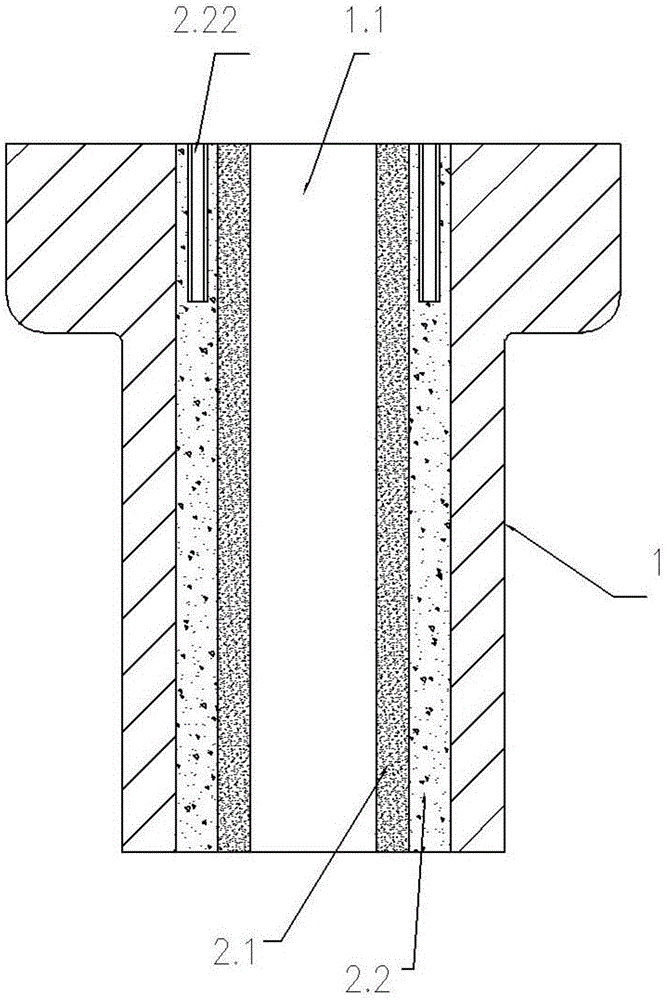
Figure 1 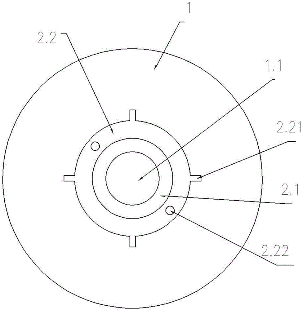
Figure 2
Abstract
Description
technical field
[0001] The invention relates to the technical field of press-fitting of fan rotors and motor shafts, in particular to an upper mold for press-fitting fan rotors and motor shafts. Background technique
[0002] In the press-fitting process of the fan rotor and the motor shaft, in order to make the motor shaft tightly fit in the center shaft hole of the fan rotor, the entire motor shaft is not made into a structure that is tightly fitted to the center shaft hole. And just stamping out on the outer peripheral wall of the tightly fitting section of the motor shaft a plurality of punching ribs arranged in the circumferential direction, so that the diameter of the tightly fitting section of the motor shaft is greater than the inner diameter of the central shaft hole to form a tight fit with the central shaft hole. The diameter of other shaft sections of the motor shaft is smaller than the inner diameter of the central shaft hole to form a clearance fit with the cent...
Examples
Embodiment Construction
[0015] The present invention will be described in further detail below in conjunction with the accompanying drawings.
[0016] As shown in the figure, the upper mold for press-fitting the fan rotor and the motor shaft of the present invention includes a steel upper mold body 1, and the upper mold body 1 is provided with an axial through hole 1.1.
[0017] The inner sleeve of the axial through hole 1.1 is provided with a combined rubber tube, and the combined rubber tube consists of an inner soft rubber tube 2.1 and an outer hard rubber tube 2.2. The inner layer of soft rubber tube 2.1 and the outer layer of hard rubber tube 2.2 are formed by injection molding through an injection mold. The outer wall of the outer hard rubber tube 2.2 is provided with a plurality of axial ribs 2.21 distributed along the circumferential direction, and the inner wall of the axial through hole 1.1 of the upper mold body 1 is provided with a plurality of axial ribs 2.21. One card matching card slo...