
Vacuum pumping side-pressing mechanism for manufacturing water-cooled clutch casing
A clutch housing and vacuum pumping technology, which is applied in the field of die-casting molds, can solve problems such as air leakage, reduce the strength of castings, and unfavorable high-efficiency production, so as to ensure the overall quality and avoid shrinkage cavities.
Patent Information
- Authority / Receiving Office
- CN · China
- Current Assignee / Owner
- Publication Date
- 2017-06-13
Smart Images
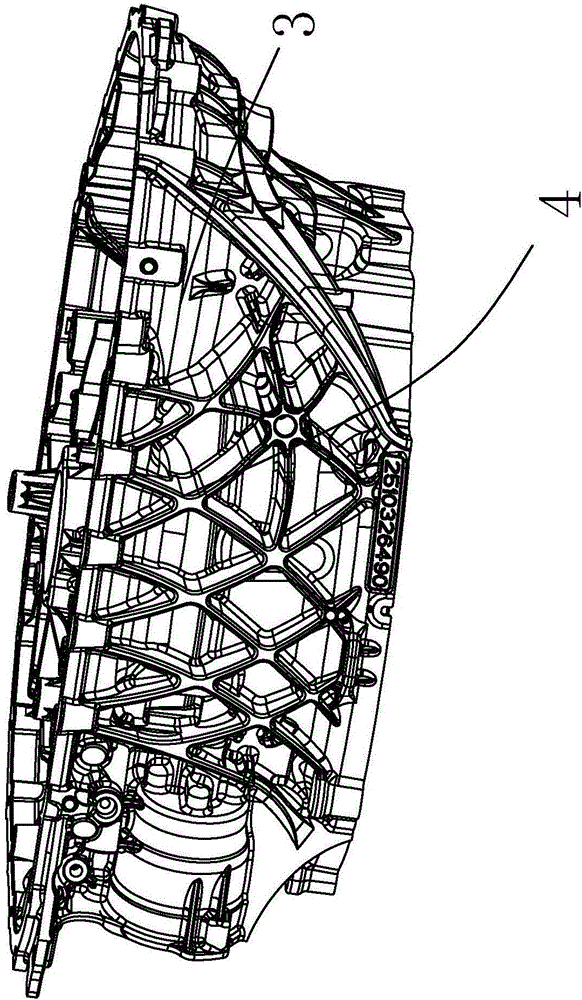
Figure 1 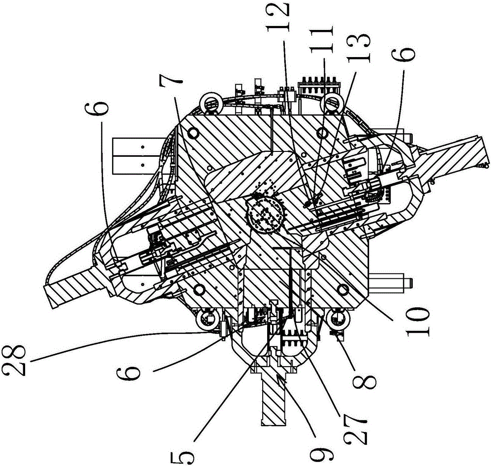
Figure 2 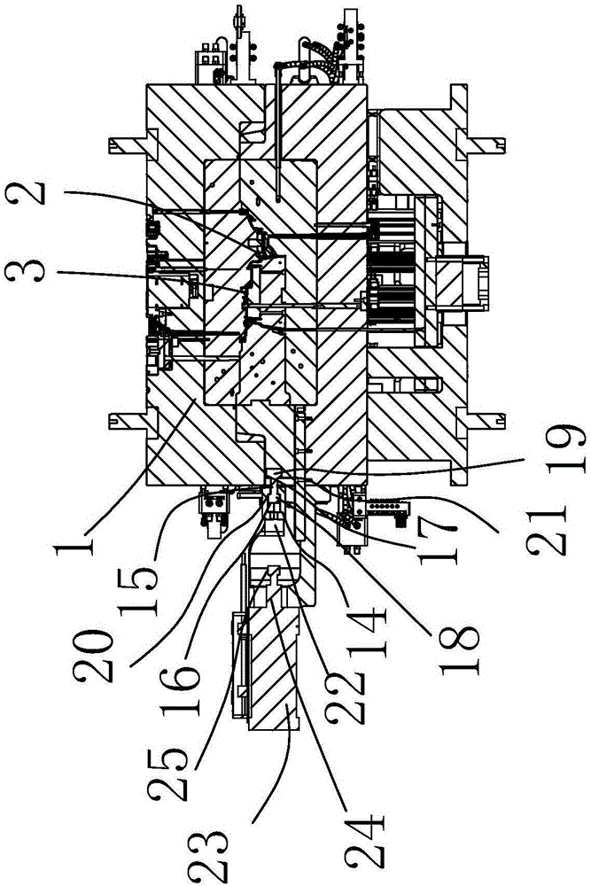
Figure 3
Abstract
Description
technical field
[0001] The invention belongs to the technical field of die-casting molds, in particular to a vacuum side pressure mechanism for manufacturing water-cooled clutch housings. Background technique
[0002] In the domestic die-casting field, air cooling is mostly used for mold cooling. With the development of cooling technology, natural room temperature full water cooling has become a new cooling method for die-casting molds. However, in this method, the mold inlet water temperature is not constant, and the cooling effect is unstable. If the temperature deviation is large, it is easy to produce shrinkage, shrinkage and cavities. Operators often rely on experience to estimate and set cooling time and other parameters within the scope of the instruction book, which is not conducive to stable casting process, not conducive to efficient production, and affects output and quality. such as production figure 1 Zhongde clutch housing 3 products, here in the thermoforming...
Examples
Embodiment Construction
[0018] The following are specific embodiments of the present invention and in conjunction with the accompanying drawings, the technical solutions of the present invention are further described, but the present invention is not limited to these embodiments.
[0019] In the figure, die-casting mold 1; injection mold cavity 2; clutch housing 3; protruding position 4; valve type vacuum device 5; side pressure device 6; side pressure top block 7; side pressure auxiliary driving block 8; side pressure driving parts 9; side pressure plug 10; oblique fixed adjustment piece 11; first oblique adjustment groove 12; second oblique adjustment groove 13; hedging piece 14; hedging rod 15; main buckle groove 16; from buckle groove 17; first Set of chucks 18; second set of chucks 19; outer limiting convex edge 20; inner limiting convex edge 21; top pressure inlet groove 22; side pressure cylinder 23; side pressure air rod 24; raised step head 25; vacuum valve 26; Vacuum tube 27.
[0020] Such...