
Refrigeration cycle system of lithium bromide jetting and absorbing type for condensation boosting
An absorption refrigeration and circulation system technology, applied in refrigerators, refrigeration components, adsorption machines, etc., can solve the problem that the condensing pressure and condensing temperature cannot be increased independently, and achieve remarkable energy saving effect, high heating medium temperature, The effect of reducing the cooling water temperature requirement
Patent Information
- Authority / Receiving Office
- CN · China
- Patent Type
- Applications(China)
- Current Assignee / Owner
- Publication Date
- 2014-11-19
Smart Images
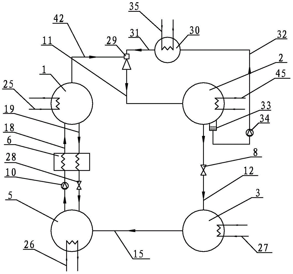
Figure 1 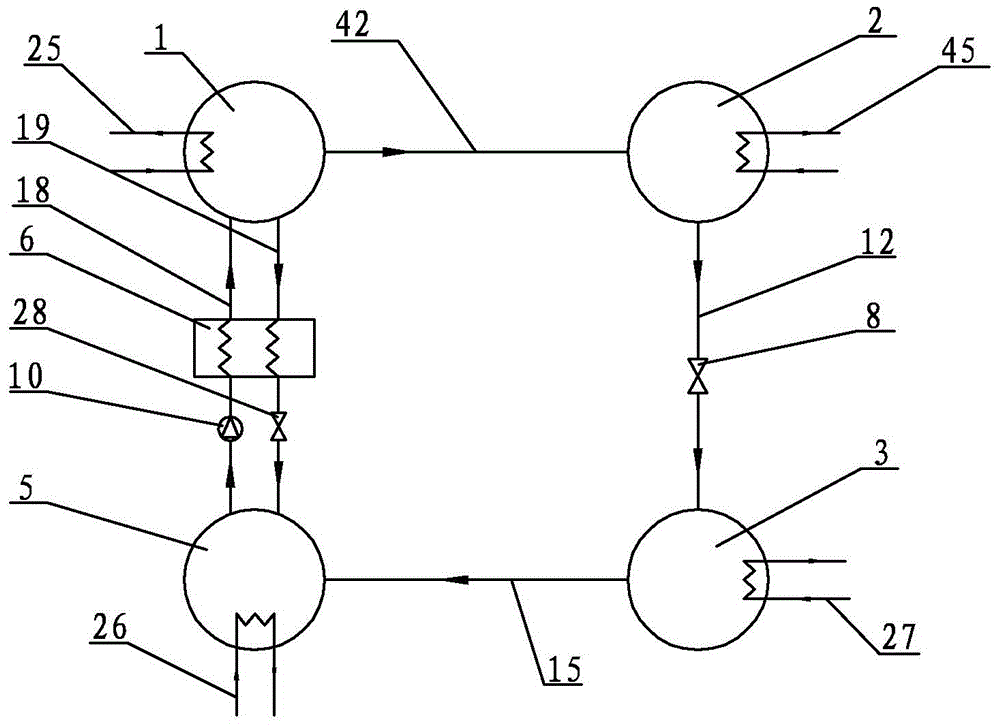
Figure 2
Abstract
Description
technical field
[0001] The invention relates to an absorption refrigerating cycle system, in particular to a condensing and boosting lithium bromide spray absorption refrigerating cycle system. Background technique
[0002] Traditional absorption refrigeration cycle systems such as figure 2 As shown, it is mainly composed of a generator 1, a condenser 2, an evaporator 3, an absorber 5, a solution heat exchanger 6, a solution pump 10, etc., and connected pipelines. Under the heating action of the first high-level heat source 25, the generator 1 condenses the lithium bromide solution in it to generate relatively high-temperature and high-pressure refrigerant water vapor and enters the condenser 2 through the first refrigerant water vapor pipeline 42 to condense, and the condensation process releases The heat is absorbed by the second cooling heat source 45, and the refrigerant water generated after condensation is throttled and depressurized by the expansion throttling device...
Examples
specific Embodiment approach 1
[0014] Specific implementation mode one: combine figure 1 Describe this embodiment, a lithium bromide injection absorption refrigeration cycle system for condensation boosting in this embodiment includes a generator 1, a condenser 2, an evaporator 3, an absorber 5, a solution heat exchanger 6, an expansion throttling device 8, Solution pump 10, throttle valve 28, first refrigerant water vapor pipeline 42, first refrigerant water passage 12, second refrigerant water vapor pipeline 15, first dilute solution pipeline 18, first concentrated solution pipe Road 19, injector 29, boiler 30, first connecting pipe 31, second connecting pipe 32, third connecting pipe 11, liquid storage device 33 and refrigerant water pump 34, condenser 2 passes through the first refrigerant water passage 12 It communicates with the evaporator 3, the expansion throttling device 8 is set on the first refrigerant water passage 12, the evaporator 3 communicates with the absorber 5 through the second refrige...
specific Embodiment approach 2
[0017] Specific implementation mode two: combination figure 1 To describe this embodiment, the steam generated in the boiler 30 of this embodiment is high-pressure refrigerant steam, and its pressure is higher than the pressure of the steam generated in the generator 1 . The high-pressure refrigerant vapor serves as the working fluid of the ejector 29 . Other components and connections are the same as those in the first embodiment.