
Dynamic angular displacement measuring device and method
A technology of angular displacement and measurement, applied in the direction of measuring devices, electric devices, instruments, etc., can solve the problems of high cost, high installation requirements, unfavorable one-time mass adoption, etc., and achieve the effect of reliable measured value and simple data analysis
Patent Information
- Authority / Receiving Office
- CN · China
- Patent Type
- Applications(China)
- Current Assignee / Owner
- Publication Date
- 2015-04-29
- Estimated Expiration
- Not applicable · inactive patent
Smart Images
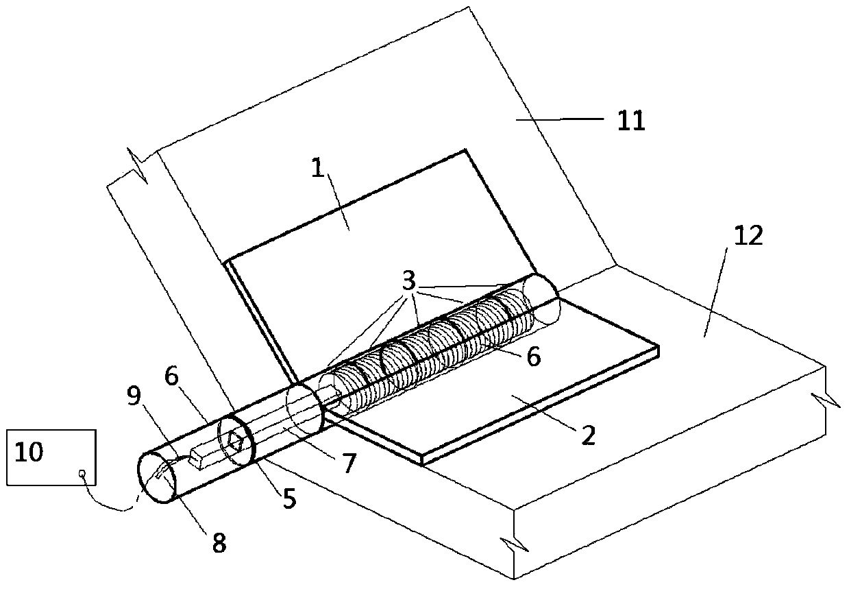
Figure 1 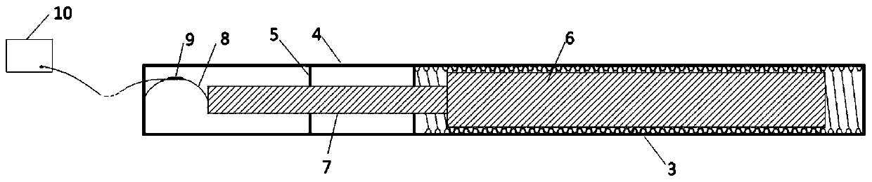
Figure 2 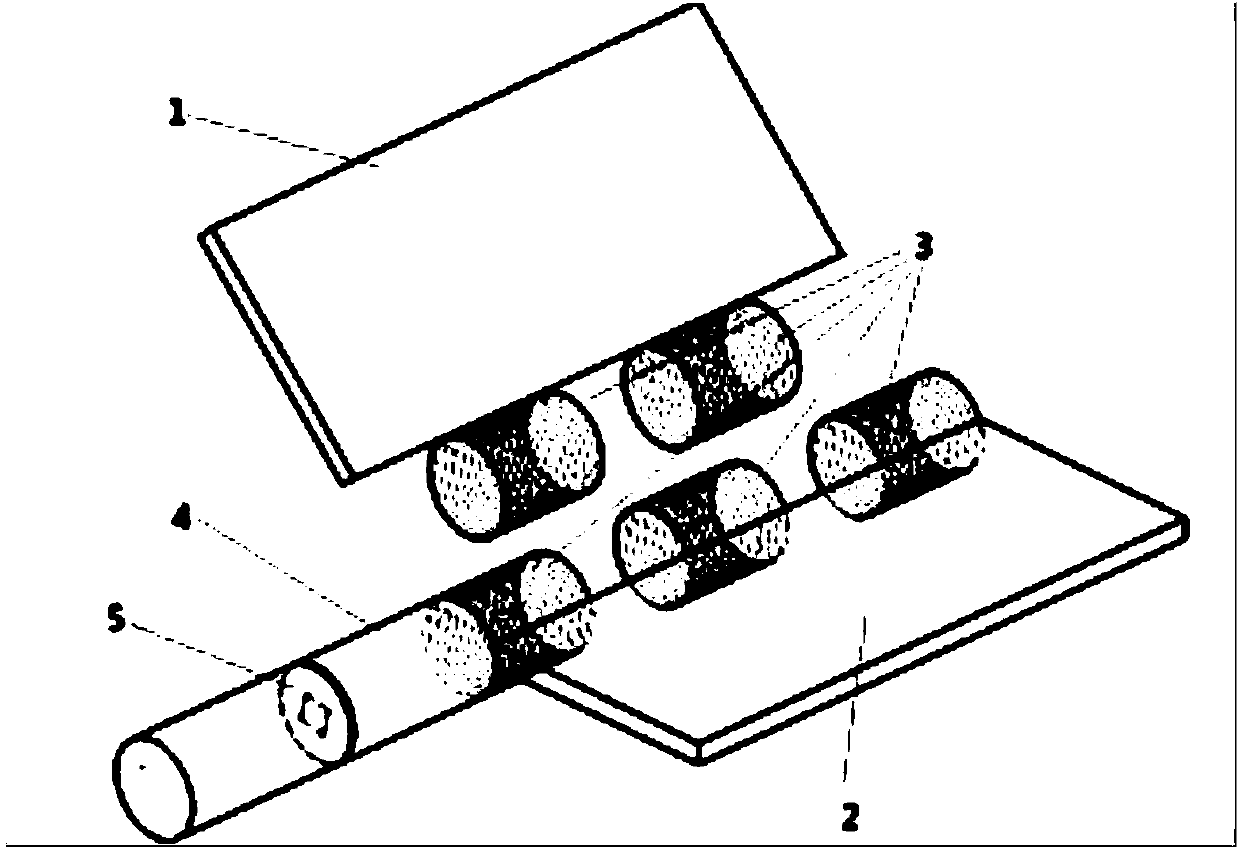
Figure 3
Abstract
Description
technical field
[0001] The invention belongs to the technical field of real-time monitoring of earthquake engineering structure deformation, and is especially suitable for rapid dynamic deformation measurement of angular displacement between engineering structure components under rapid loading conditions such as earthquakes and electromechanical vibrations, and is suitable for small-scale model tests or engineering monitoring. In particular, a device for dynamically measuring angular displacement is adopted, which converts dynamic angular displacement measurement into linear displacement measurement. Background technique
[0002] Under dynamic loads such as earthquakes and electromechanical vibrations, there will be continuous dynamic and rapid changes in relative angular displacement between structural components, such as measuring the dynamic angular displacement of the consolidation end of a steel structure cantilever beam in civil engineering. The magnitude of the angle ...
Examples
Embodiment Construction
[0013] The specific embodiments of the present invention will be described in detail below in conjunction with the technical solutions and accompanying drawings.
[0014] As shown in the figure, the threaded sleeve 3 is arranged in the interval on one side of the metal plate a, and the threaded sleeve 3 is also intermittently arranged on one side of the metal plate b, so as to ensure that the central axis of the threaded sleeve 3 is in line with the two metal plates. The axes of rotation of the lower surfaces coincide. A sleeve 4 with the same diameter as the threaded sleeve 3 is externally connected to one end of the threaded sleeve 3 to ensure that the central axes of the metal sleeve 5 and the threaded sleeve 3 are on the same straight line, and a limit is set in the sleeve 4 Hole 5.
[0015] As shown in the figure, the threaded sleeves 3 are engaged with each other, so that the two metal plates can rotate around the central axis of the threaded sleeves 3 . The precision ...