
A delay start overcurrent protection circuit
A technology of overcurrent protection circuit and delayed start, applied in emergency protection circuit devices, emergency protection devices with automatic disconnection, circuit devices, etc., can solve the problem of inability to act immediately, and achieve rapid response, simple structure, and versatility. strong effect
Patent Information
- Authority / Receiving Office
- CN · China
- Patent Type
- Patents(China)
- Current Assignee / Owner
- Publication Date
- 2018-03-16
- Estimated Expiration
- Not applicable · inactive patent
Smart Images
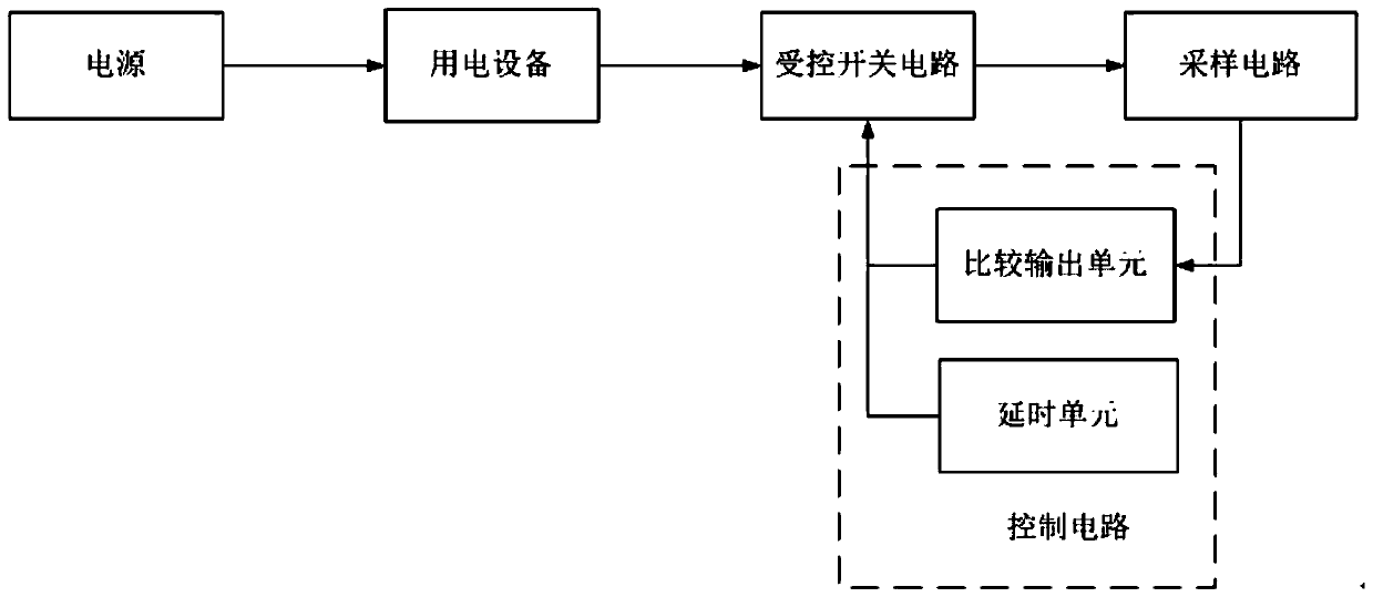
Figure 1 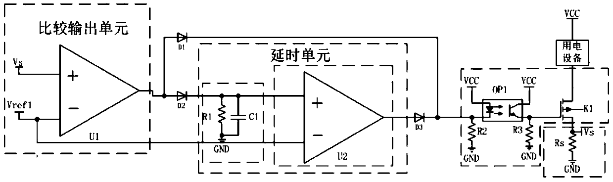
Figure 2
Abstract
Description
technical field
[0001] The invention belongs to the technical field of circuit design, in particular to an overcurrent protection circuit with delayed start. Background technique
[0002] Overcurrent protection is also called overload protection. Overload means that the load is too large, exceeding the rated load of the device itself. The phenomenon of overload is that the current is too large, and the electrical equipment heats up. The long-term overload of the line will reduce the insulation level of the line, or even burn the equipment or line. Therefore, the corresponding equipment should be protected by an over-current protection circuit, and a reasonable over-current threshold should be set in the over-current protection circuit.
[0003] The overcurrent protection circuit disclosed in the prior art generally includes a sampling unit, a comparison unit, and a control unit. The sampling unit is used to sample the real-time current of the loop and convert it into a real...
Examples
Embodiment Construction
[0018] The present invention will be further introduced below in conjunction with the accompanying drawings and specific embodiments.
[0019] Such as figure 1 Shown is the functional block diagram of the overcurrent protection circuit with delayed start of the present invention. It can be seen from the figure that the circuit includes a controlled switch circuit and a sampling circuit for connecting in series with the electrical equipment, and the power supply terminal of the electrical equipment is connected to the power supply; The signal output terminal of the sampling circuit is connected to the control circuit, and the output terminal of the control circuit is connected to the control terminal of the controlled switch circuit. The control circuit includes a comparison output unit and a delay unit, and the output terminals of the comparison output unit and the delay unit are connected to the The control terminal of the controlled switch circuit is connected; the compariso...