
Grain collection device
A collection device and grain technology, applied in the field of machinery, can solve the problems of large fan size, many parts, long process, etc., and achieve the effect of improving production efficiency, fewer parts and simple structure
Patent Information
- Authority / Receiving Office
- CN · China
- Patent Type
- Patents(China)
- Current Assignee / Owner
- Publication Date
- 2017-03-29
Smart Images
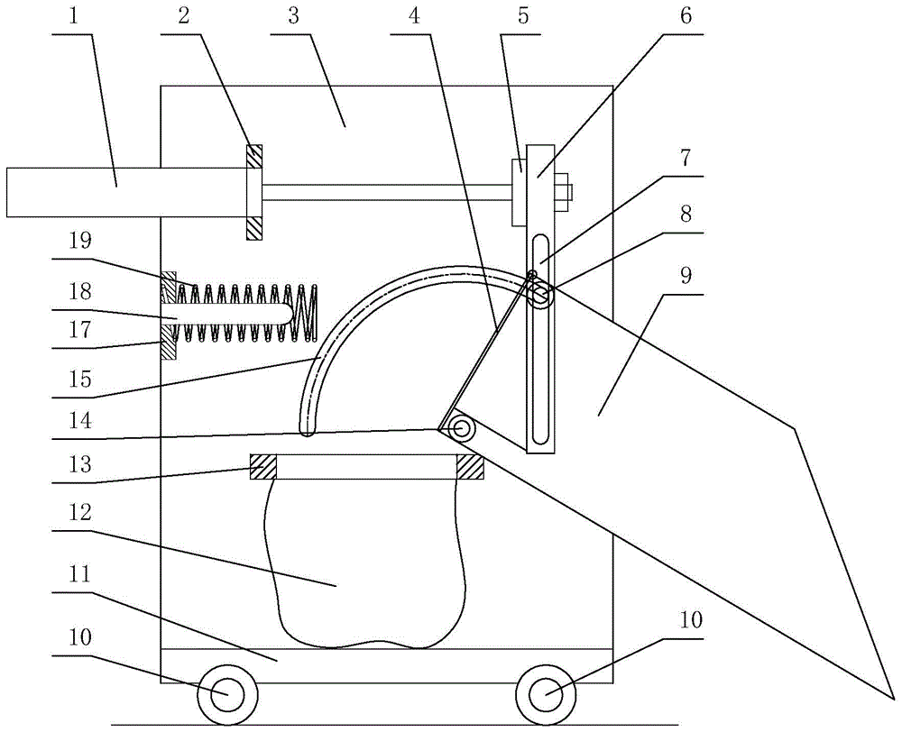
Figure 1 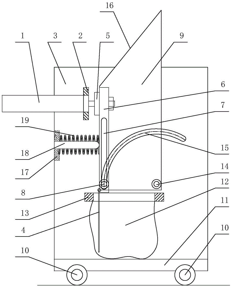
Figure 2 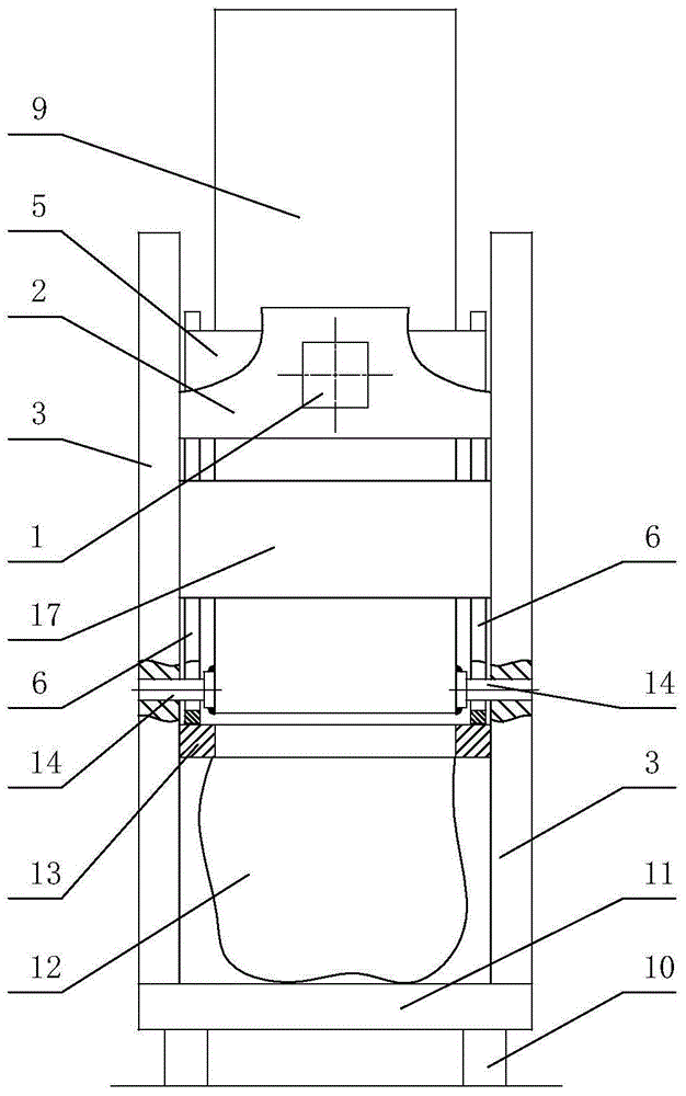
Figure 3
Abstract
Description
technical field
[0001] The invention relates to the technical field of machinery, in particular to a grain collecting device. Background technique
[0002] Summer and autumn are the time periods for farmers and grain storage units to store grain in a centralized manner. Therefore, the grain needs to be bagged in the granary for better grain storage in the later period. In the prior art, most of the staff in the granary bag the grain manually. On the one hand, the labor efficiency is low. laborious.
[0003] Therefore, mechanical bagging devices appear on the market to improve production efficiency. For example, the patent number "ZL201210230214.9" disclosed on the website of the State Intellectual Property Office for the invention patent of "grain automatic collection and bagging machine" includes a grain leakage cleaning device, a auger, a grain distributing device, an elevator, and wind impurity removal. Device, grain feeding mechanism, vibrating screen and magnetic cle...
Examples
Embodiment Construction
[0026] The present invention will be described in further detail below with reference to the accompanying drawings and specific embodiments.
[0027] Depend on Figure 1 to Figure 3 It can be seen from the schematic structural diagram of the grain collection device of the present invention that it includes a movable base 11, a rack plate 3, a bag fixing device 13 for sleeved grain bags 12, a hopper 9, a hopper drive device and a hopper buffer device. . There are two rack plates 3, and the lower end of each rack plate 3 is fixedly connected to the edge of the movable base 11; the bag fixing device 13 is connected between the two rack plates 3 and is located in the rack. The middle of the plate 3 in the vertical direction. The hopper 9 is rotatably attached to the two frame plates 3 and the rotatable attachment point is located above the edge of the bag holder 13 . The hopper driving device includes a driving cylinder 1, two vertical sliding rods 6, a sliding rod connecting p...