
Safety protection circuit of blade electric vehicle motor
A safety protection circuit, pure electric vehicle technology, applied in the direction of emergency protection circuit devices, electrical components, etc., can solve the problems of lack of vehicle safety, inability to guarantee motor misoperation, etc., to achieve the effect of reliable and reliable protection of the circuit
Patent Information
- Authority / Receiving Office
- CN · China
- Patent Type
- Applications(China)
- Current Assignee / Owner
- Publication Date
- 2016-05-18
- Estimated Expiration
- Not applicable · inactive patent
Smart Images
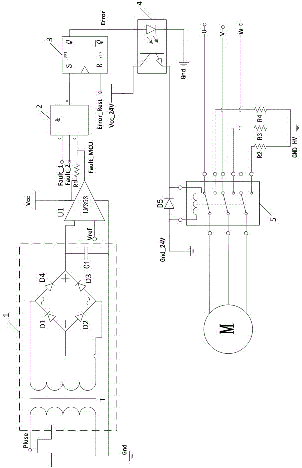
Figure 1
Abstract
Description
technical field
[0001] The invention relates to the technical field of automatic control of electric vehicles, in particular to a safety protection circuit for pure electric vehicle motors. Background technique
[0002] Pure electric vehicles are generally driven by high-voltage motors. If the motor controller fails, the output torque of the motor will be too small or too large, the speed of the motor will be uncontrollable, or the high voltage of the drive will leak. Any of the above phenomena is beyond the control of the vehicle driver. Once it occurs, it will damage the vehicle, affect the safe driving of the vehicle, and seriously endanger the personal safety of the driver.
[0003] At present, the measures adopted mainly focus on the monitoring of the three-phase current of the motor, mainly current phase loss detection, current peak detection, etc., and the measures taken are to turn off the motor drive signal. If the drive circuit also fails when the current fault ...
Examples
Embodiment Construction
[0012] Such as figure 1 As shown, a safety protection circuit for a pure electric vehicle motor includes a pulse signal rectification and filtering circuit 1 for receiving a pulse signal output by a microcontroller MCU in a motor controller, and its output terminal is connected to the input terminal of a voltage comparison circuit. The output end of the voltage comparison circuit is connected with the input end of the multi-signal logic operation circuit 2, the output end of the multi-signal logic operation circuit 2 is connected with the input end of the fault latch and reset circuit 3, and the output end of the fault latch and reset circuit 3 It is connected to the input end of the high-voltage isolation circuit 4, the output end of the high-voltage isolation circuit 4 is connected to the control end of the relay in the relay control circuit 5, and the three-phase drive signals U, V, W of the motor controller pass through the normally closed end of the relay It is connected ...