
Characteristic coincidence degree comparison method for onsite defect linear trace
A linear trace and coincidence technology, applied in the field of criminal investigation science, can solve the problems of high price and cost, loss, etc., and achieve the effect of improving efficiency and wide practicability
Patent Information
- Authority / Receiving Office
- CN · China
- Patent Type
- Applications(China)
- Current Assignee / Owner
- Publication Date
- 2016-06-15
Smart Images
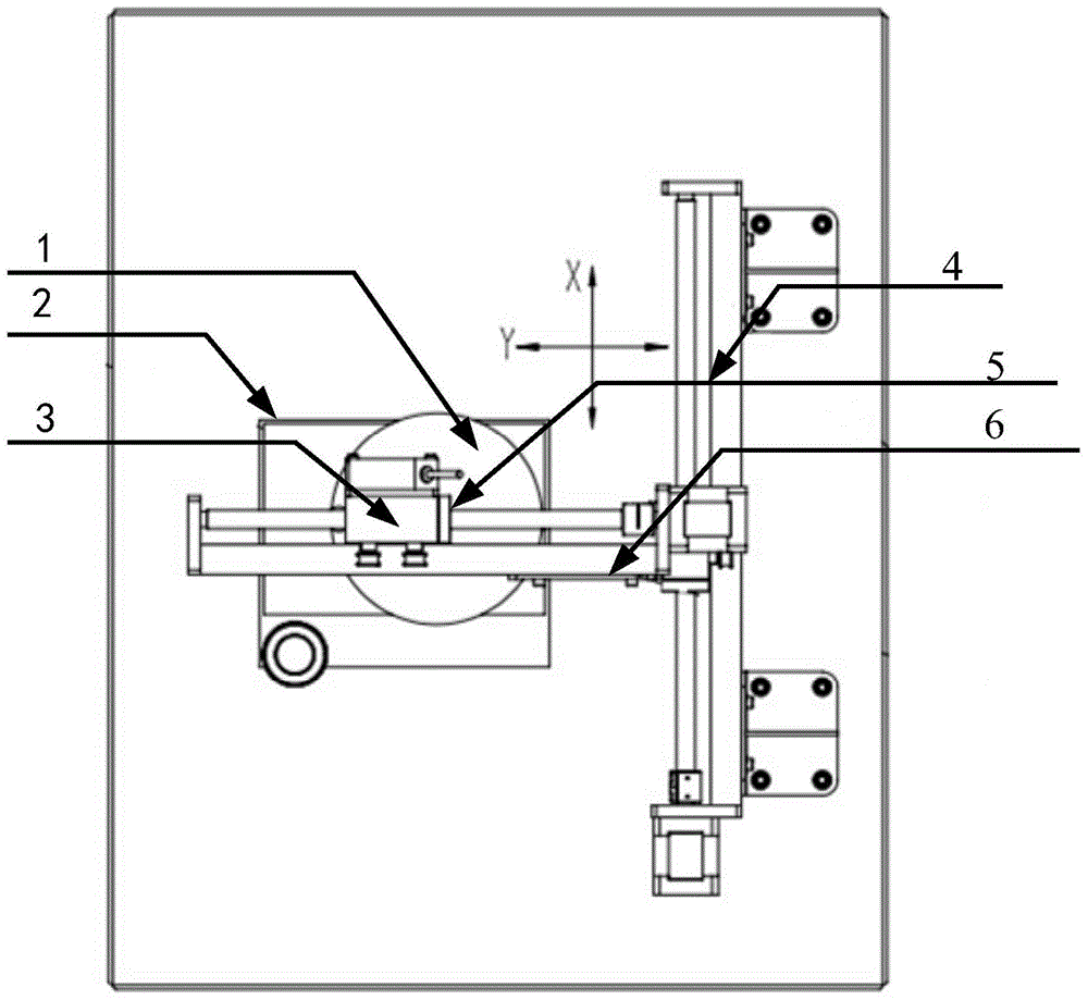
Figure 1 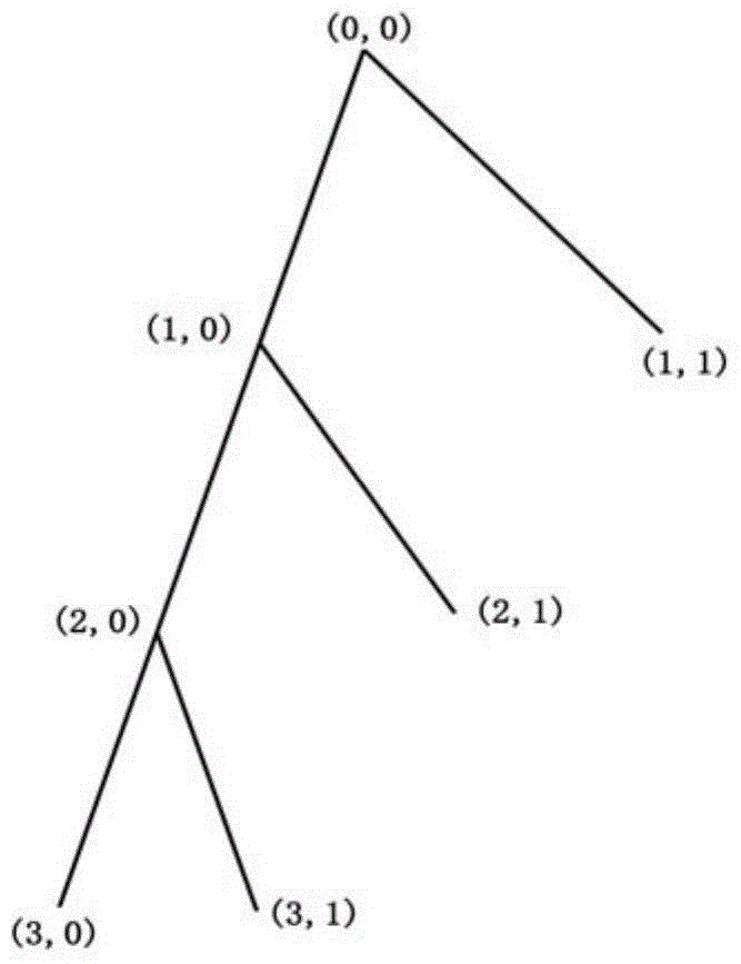
Figure 2 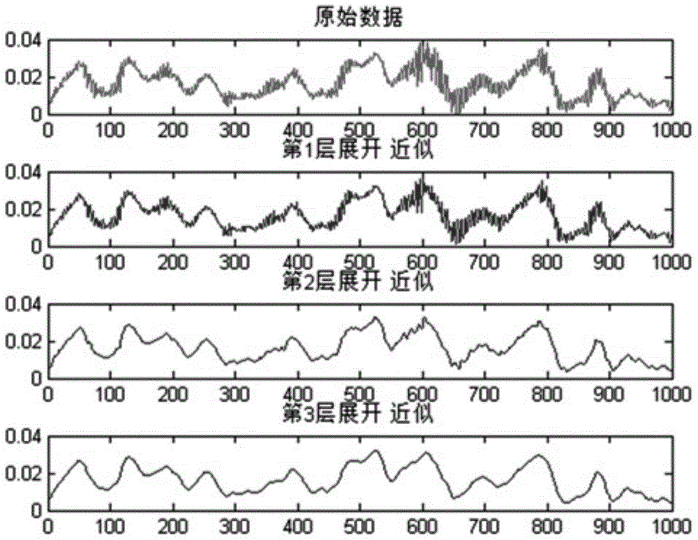
Figure 3
Abstract
Description
technical field
[0001] The invention relates to a method for comparing coincidence degrees of incomplete linear trace features on the spot, belonging to the technical field of criminal investigation. Background technique
[0002] As we all know, the railway is an important infrastructure of the country, and it is also the main artery of national economic development, especially the rapid development of high-speed rail has made it a popular means of transportation and the backbone of the comprehensive transportation system; important role in development.
[0003] The high-speed development of the railway has also brought some hidden dangers. Because there are a large number of high-quality communication cables along the railway, and there are great difficulties in the management along the railway, this has caused some criminals to steal cables. Phenomenon. For the theft of cables, cutting tools are often used to cut cables, leaving only the ends of the cutting type. How to ...
Examples
Embodiment 1
[0036] Embodiment 1: as Figure 1-7 As shown, a method for comparing the coincidence degree of incomplete linear trace features on the spot, the specific steps of the coincidence degree comparison method for the incomplete linear trace features on the spot are as follows:
[0037] Step 1. Use the laser displacement sensor of the linear trace laser detection test bench device to horizontally detect the incomplete linear trace surface on the trace bearing body to form a detection signal waveform f(x);
[0038] Step2. Through wavelet decomposition, the laser detection signal waveform f(x) is subjected to data smoothing processing to eliminate background noise interference and obtain a smoothed signal f 1 (x);
[0039] In the step Step2, the specific steps are:
[0040] Step2.1. Decompose the original signal into two parts according to the following formula:
[0041] f = a n + Σ i ...
Embodiment 2
[0051] Embodiment 2: as Figure 1-7 As shown, a method for comparing coincidence degree of on-site incomplete linear trace features, this embodiment is the same as Embodiment 1, the difference is that this embodiment is explained with an actual case:
[0052] The specific steps of the on-site incomplete linear trace feature coincidence degree comparison method are as follows:
[0053] Step 1. Use the laser displacement sensor of the linear trace laser detection test bench device to horizontally detect the incomplete linear trace surface on the trace bearing body to form a detection signal waveform f(x);
[0054] Step2. Through wavelet decomposition, the laser detection signal waveform f(x) is subjected to data smoothing processing to eliminate background noise interference and obtain a smoothed signal f 1 (x);
[0055] Such as Figure 2-3 As shown, in the actual noise reduction process, the original signal f(t) needs to be decomposed into multiple layers. The more layers ar...