
Filtering method adopting wave suppression, magnetization, adsorption and rotating magnetic field
A technology of rotating magnetic field and filtering method, which is applied in fluid pressure actuating devices, fluid pressure actuating system components, mechanical equipment, etc., and can solve problems such as different cleanliness requirements, reduced service life of filter elements, and decreased filtration speed. Achieve the effects of reducing filtering cost and complexity, suppressing the increase of filter cake thickness, and improving service life
Patent Information
- Authority / Receiving Office
- CN · China
- Current Assignee / Owner
- Publication Date
- 2016-08-17
- Estimated Expiration
- Not applicable · inactive patent
Smart Images
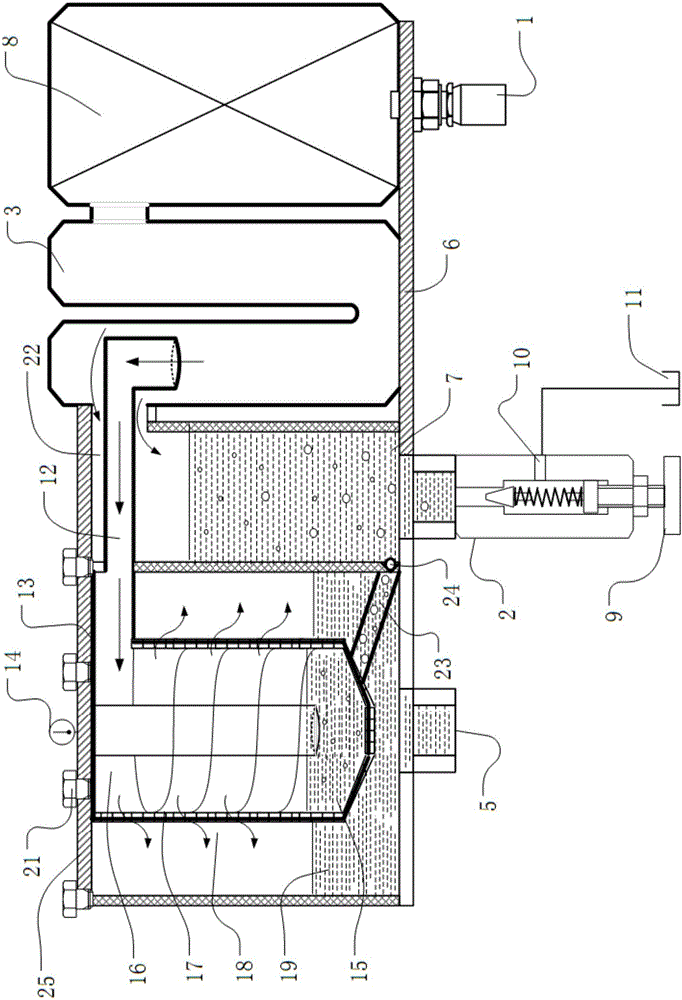
Figure 1 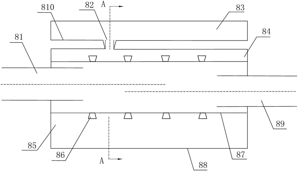
Figure 2 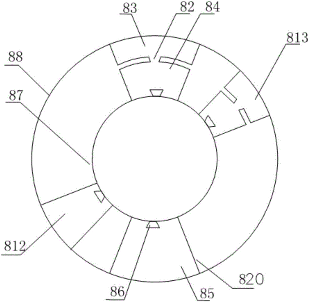
Figure 3
Abstract
Description
Technical field
[0001] The invention relates to a hydraulic oil filtering method, in particular to a filtering method using wave suppression, magnetization, adsorption and rotating magnetic field, and belongs to the technical field of hydraulic equipment.
Background technique
[0002] Statistics at home and abroad show that about 70% to 85% of hydraulic system failures are caused by oil pollution. Solid particles are the most common and harmful pollutants in oil pollution. Hydraulic system failures caused by solid particle pollutants account for 70% of total pollution failures. Metal debris accounts for 20% to 70% of the particle pollutants in hydraulic system oil. Taking effective measures to filter out the solid particle pollutants in the oil is the key to the pollution control of the hydraulic system, and it is also a reliable guarantee for the safe operation of the system.
[0003] Filters are key components of hydraulic systems to remove solid particle contaminan...
Examples
Embodiment Construction
[0050] Please refer to the attached figure 1 To attach Figure 17 As shown, the present invention is a filter device using wave suppression, magnetization, adsorption and rotating magnetic field, which consists of a bottom plate 6, a filter 8, a U-shaped particle separation module 3, an oil return cylinder 7, an inner cylinder 15, and a spiral flow channel 17, several parts such as filter element 18, outer tub 19 and end cap 25 are formed. Wherein, the filter 8 , the U-shaped particulate separation module 2 , the oil return cylinder 7 , and the outer barrel 19 are placed on the bottom plate 6 in sequence.
[0051] The filter 8 is used to input the hydraulic oil, and can attenuate the pulsating pressure in the high, medium and low frequency bands in the hydraulic system, and suppress the flow fluctuation. The filter 8 is composed of an input tube 81 , a casing 88 , an output tube 89 , an elastic thin wall 87 , an H-type filter 812 and a series H-type filter 813 .
[0052] Wh...