
A new wheel hub manual surface drawing machine
A technology of wire drawing machine and wheel hub, which is applied in the field of new wheel hub manual surface drawing machine, can solve the problems of inability to guarantee the quality of wheel hub wire drawing and unstable force, and achieve the effect of satisfying product shape and reducing labor intensity
Patent Information
- Authority / Receiving Office
- CN · China
- Patent Type
- Patents(China)
- Current Assignee / Owner
- Publication Date
- 2017-11-03
Smart Images
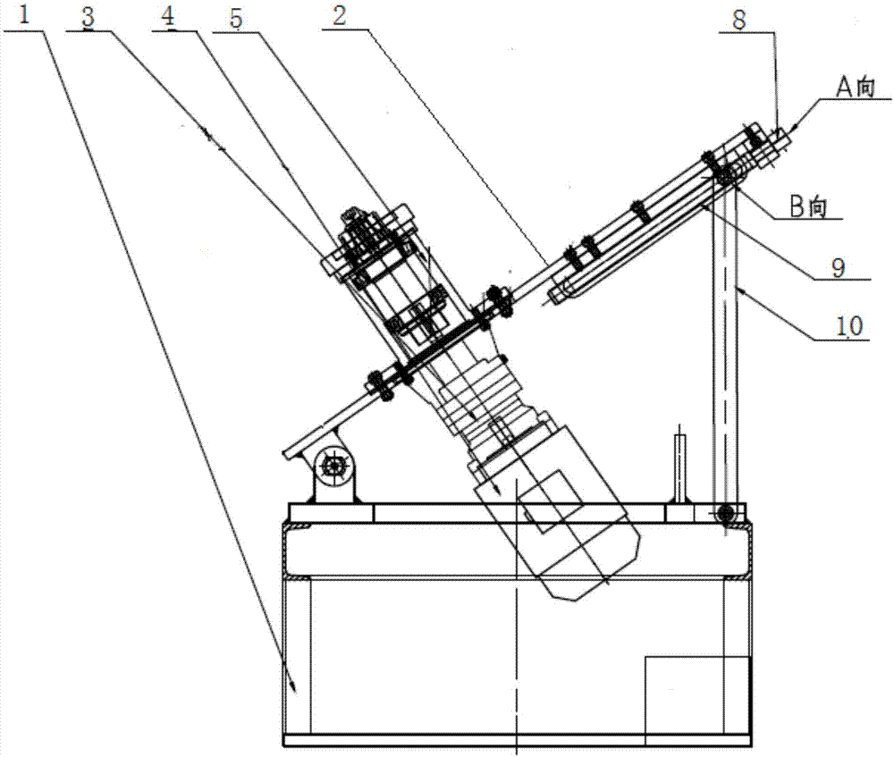
Figure 1 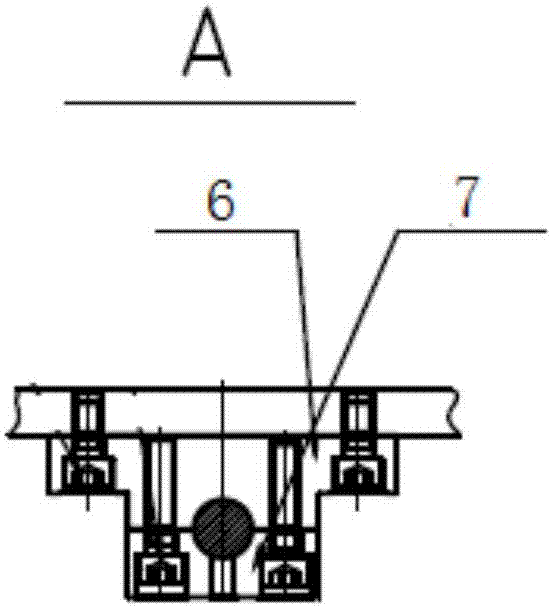
Figure 2 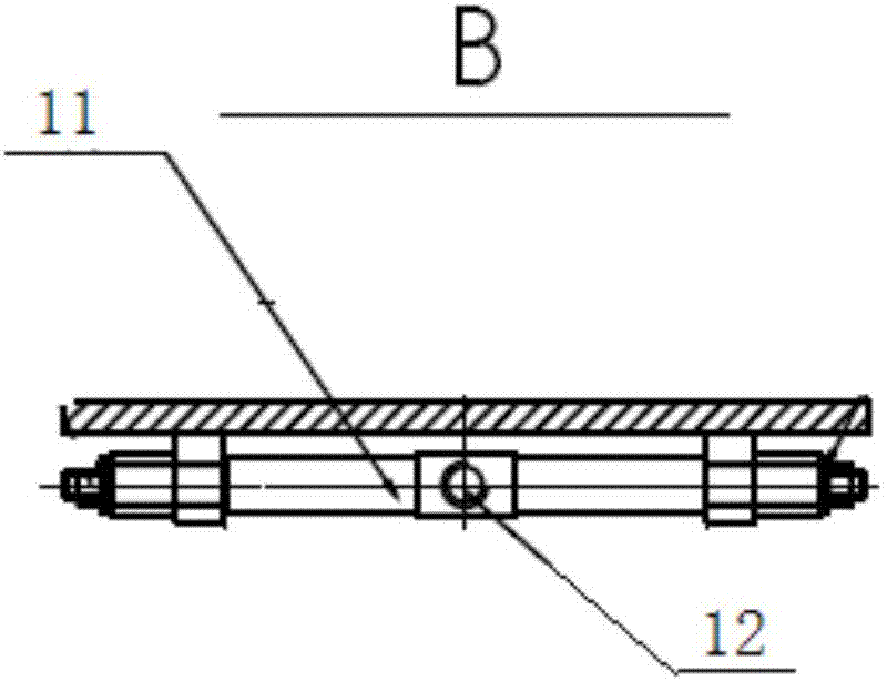
Figure 3
Abstract
Description
technical field
[0001] The invention belongs to the field of mechanical engineering, in particular to a novel wheel hub manual surface drawing machine. Background technique
[0002] Drawing patterns on the surface of the hub can not only improve the appearance quality of the hub surface, but also improve the performance of the hub surface being corroded. Therefore, the new wheel hub manual surface drawing machine is an important process device. Machines put the hub directly on the platform, and then carry out the surface drawing process. Since the drawing process is carried out along the periphery of the wheel hub surface, the action point of the wheel hub drawing process is to move along the periphery of the wheel hub surface, and the wheel hub cannot be adjusted. The action point of the wire drawing process is a fixed point, which increases the difficulty for the operator to stabilize the force of the wire drawing process, and cannot guarantee the quality of the wheel hub ...
Examples
Embodiment Construction
[0030] In order to further understand the content, features and effects of the present invention, the following examples are given, and detailed descriptions are given below with reference to the accompanying drawings.
[0031] see Figure 1 to Figure 8 :
[0032] A new wheel hub manual surface drawing machine, including a bracket 1, a rotating plate 2, a reducer 3, a motor 4, a rotating shaft combination 5, a transmission shaft fixing base 6, a transmission shaft tight seat 7, a transmission shaft 8, a chute 9, and a crank Rod 10, rotating plate sliding shaft 11, rotating plate sliding shaft stop ring 12;
[0033] The reducer 3 is mounted on the output shaft end of the motor 4, the rotating plate 2 is hingedly mounted on the support 1, and the reducing device 3 and the motor 4 are connected with the rotating plate 2 as a whole by bolts. ;
[0034] The rotating shaft 5-2 in the rotating shaft combination 5 is connected with the output shaft of the reducer 3 through a flat k...