
Pipeline compressor model stage with flow coefficient being 0.0266 and impeller design method
A pipeline compressor and flow coefficient technology, which is applied in the field of compressors to achieve the effects of high energy head coefficient, reduced working speed and large wheel-to-hub ratio.
Patent Information
- Authority / Receiving Office
- CN · China
- Patent Type
- Applications(China)
- Current Assignee / Owner
- Publication Date
- 2017-02-08
- Estimated Expiration
- Not applicable · inactive patent
Smart Images
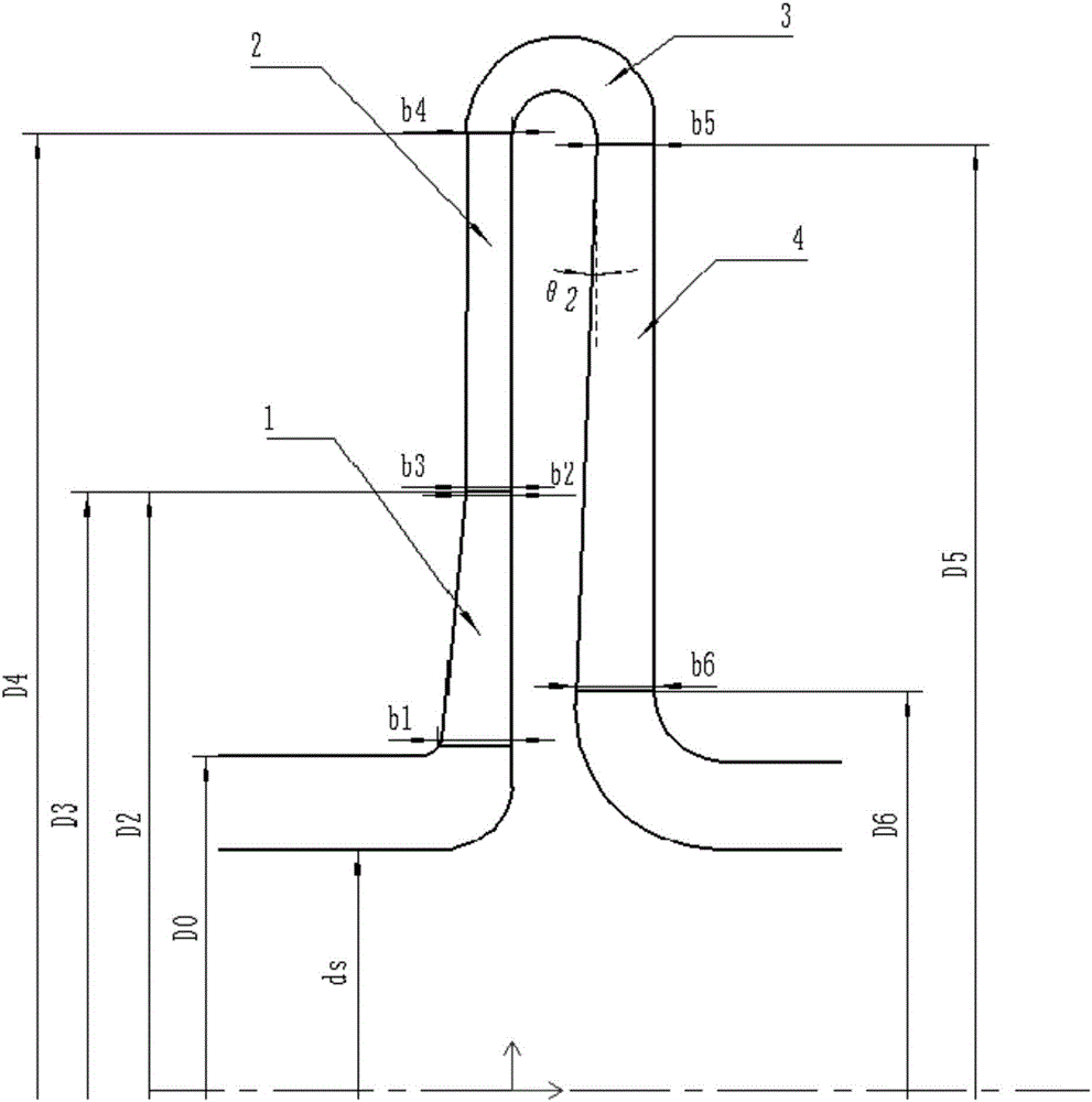
Figure 1 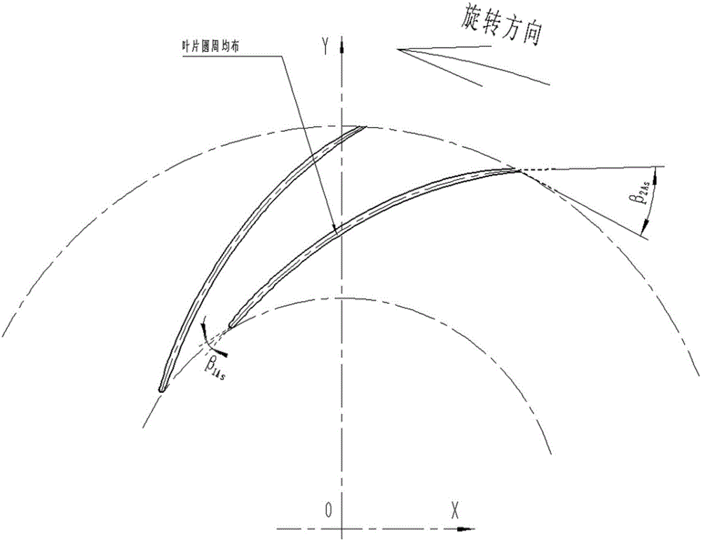
Figure 2 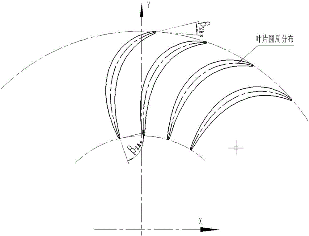
Figure 3
Abstract
Description
technical field
[0001] The invention relates to the technical field of compressors, in particular to a model stage and impeller design method of a pipeline compressor with a flow coefficient of 0.0266. Background technique
[0002] The pipeline compressor is the key equipment of the national key project of the West-to-East Gas Pipeline. During its research and development process, the design of the model level is very critical, and the development of new products depends on the corresponding model level.
[0003] The existing pipeline model stage has disadvantages such as small wheel-to-hub ratio, large axial span, and low efficiency. Therefore, in the process of product design, the shaft diameter is small and the shaft length is long, and the critical speed of the product, the stability of the rotor, and the stiffness of the shaft, etc. There are big problems in this aspect, which brings great difficulties to product design. In addition, the performance of the unit is lowe...
Examples
Embodiment Construction
[0039] see figure 1 , a pipeline compressor model stage with a flow coefficient of 0.0266 provided by the embodiment of the present invention is suitable for the modeling design of pipeline compressors and other light medium compressor products, including impeller 1, vaneless diffuser 2, bend 3 and A reflux device 4, wherein the impeller 1 is located at the inlet of the model stage, a vaneless diffuser 2 is provided at the outlet of the impeller 1, and the reflux device 4 is located at the outlet of the model stage, between the vaneless diffuser 2 and the reflux device 4 3 connected through the bend. The machine Mach number M that can be used by this model level a2 =0.35~0.65, design point flow coefficient The design point energy head coefficient τ=0.586, the variable efficiency η under the design flow coefficient working condition at each Mach number pcl =0.83~0.833, the applicable flow range is 60%-150% of the design point. Specific performance curves such as Figures ...