
Reluctance magnetic suspension linear motor
A linear motor and magnetic levitation technology, applied in electromechanical devices, electrical components, electric components, etc., can solve the problems of limiting the excellent performance of ordinary linear motors, and achieve the effects of stable and reliable suspension operation, maintenance-free, and improved motor life.
Patent Information
- Authority / Receiving Office
- CN · China
- Patent Type
- Applications(China)
- Current Assignee / Owner
- Publication Date
- 2018-09-28
- Estimated Expiration
- Not applicable · inactive patent
Smart Images
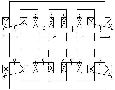
Figure 1 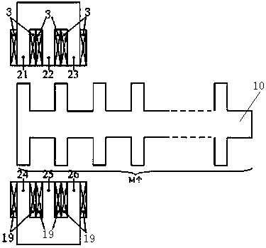
Figure 2 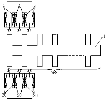
Figure 3
Abstract
Description
technical field
[0001] The invention relates to the technical field of motor manufacturing, in particular to a reluctance type magnetic levitation linear motor with no friction and wear, simple control, reliable operation, strong load capacity, fast response speed and accurate positioning. Background technique
[0002] With the rapid development of automatic control technology and microcomputers, higher requirements are placed on the positioning accuracy of linear motion control systems. The linear motion drive device composed of a traditional rotating motor and a set of transformation mechanisms has been difficult to meet the requirements of modern linear motion control systems. Performance requirements, the direct drive of the linear motion load by the linear motor has the following advantages: ①. The structure is simple, because the linear vibration motor does not need additional devices to convert the rotary motion into a linear motion, so the structure of the system itse...
Examples
Embodiment Construction
[0019] Such as figure 1 , 2 , a reluctance type magnetic levitation linear motor shown in 3, 4, 5, 6, including an upper stator, a lower stator and a mover, the upper stator includes a left upper side suspension core 2, a right upper side suspension core 5, a left upper side control Iron core 7 and upper right control core 8; the side view projections of the upper left suspension core 2 and the upper right suspension core 5 have a U-shaped structure, and the U-shaped teeth of the upper left suspension core 2 and the upper right suspension core 5 are respectively wound with the first The suspension winding 1 and the sixth suspension winding 6; the upper left control core 7 and the upper right control core 8 have an E-shaped structure in side view projection, and the E-shaped teeth of the upper left control core 7 and the upper right control core 8 are respectively wound with third The axial control winding 3 and the fourth axial control winding 4; the lower stator includes a l...