
Apparatus for eliminating harmful plants
A technology of harmful plants and organisms, applied in the field of agriculture and forestry, can solve the problems of increased processing costs, single structure, and inability to disintegrate harmful plants
Patent Information
- Authority / Receiving Office
- CN · China
- Patent Type
- Applications(China)
- Current Assignee / Owner
- Publication Date
- 2018-11-06
- Estimated Expiration
- Not applicable · inactive patent
Smart Images
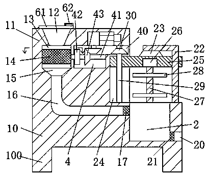
Figure 1 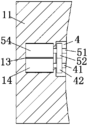
Figure 2 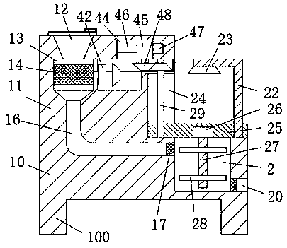
Figure 3
Abstract
Description
technical field
[0001] The invention relates to the technical field of agriculture and forestry, in particular to a device for eliminating harmful plants. Background technique
[0002] During the cultivation of agricultural and forestry crops, wild plants are often encountered among the crops. Some wild plants themselves will harm the growth of cultivated crops during the growth process. Therefore, it is necessary to remove harmful plants to ensure the normal growth of cultivated crops. The traditional removal method digs out the harmful plants and piles them on the field. This extensive removal method will cause the harmful plants to grow again with the help of the soil. Therefore, these plants need to be broken up to prevent the re-growth, so as to achieve Thorough cleaning, the current crushing equipment has a single structure and cannot crush large harmful plants. It needs to be treated separately, which increases the processing cost and does not meet the actual needs. ...
Examples
Embodiment Construction
[0020] The preferred embodiments of the present invention will be described in detail below in conjunction with the accompanying drawings, so that the advantages and features of the present invention can be more easily understood by those skilled in the art, so as to define the protection scope of the present invention more clearly.
[0021] refer to Figure 1-4 The shown device for eliminating harmful plants includes a lower body 10 and an upper body 11 as a whole, the bottom of the lower body 10 is fixed with a pillar 100, and the upper body 11 is located at the top left end of the lower body 10, A stirring chamber 2 is arranged on the right end surface of the top of the lower body 10, a frame body 22 is arranged on the right end of the top top of the lower body 10, and an outer discharge hole 20 communicating with the stirring chamber 2 is arranged on the right end surface of the lower body 10. , the first valve body 21 is set in the outer discharge hole 20, the disintegrat...