
Primary oil-water separation filtration structure
A technology of preliminary separation and filtration structure, applied in the directions of liquid separation, separation method, dispersed particle separation, etc., can solve the problems of escape and oil stains that cannot be completely separated, and achieve the advantages of less water content, improved gas emission quality, and improved separation accuracy. Effect
Patent Information
- Authority / Receiving Office
- CN · China
- Current Assignee / Owner
- Publication Date
- 2019-03-08
- Estimated Expiration
- Not applicable · inactive patent
Smart Images
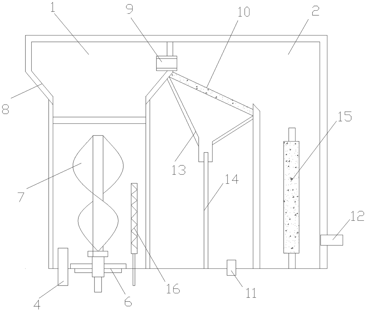
Figure 1 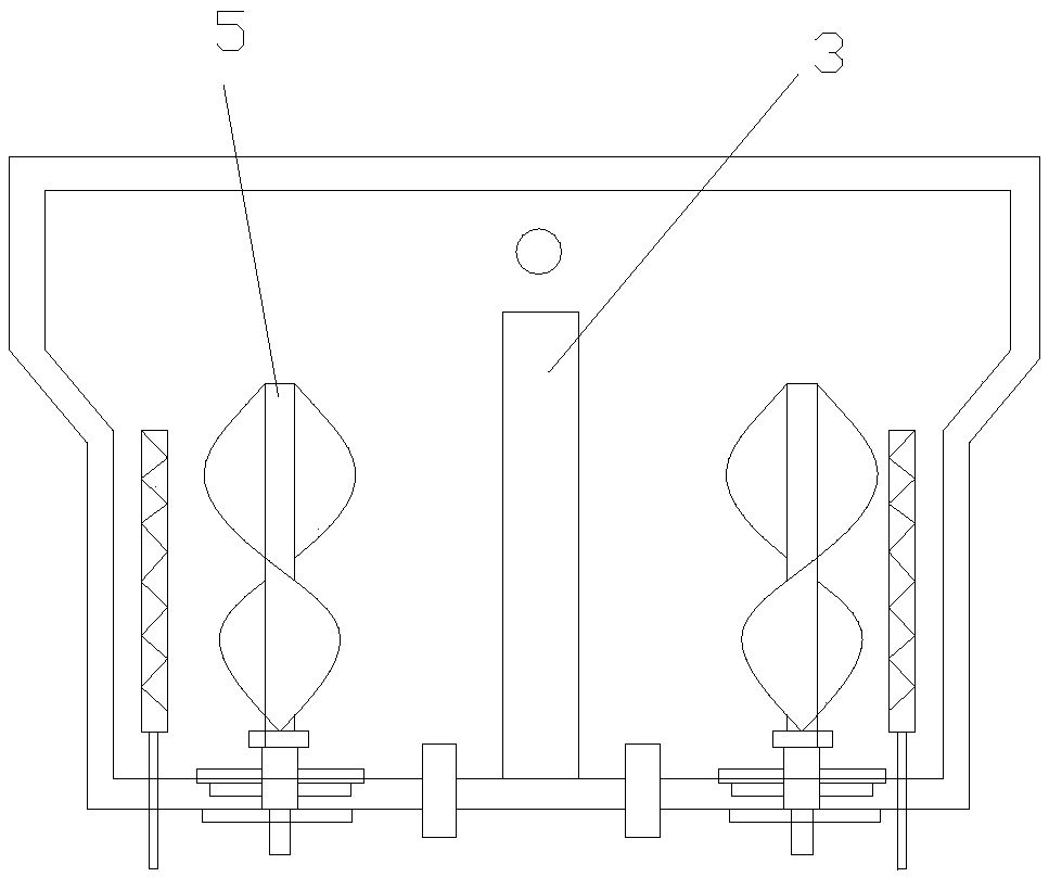
Figure 2
Abstract
Description
technical field
[0001] The invention relates to the field of garbage treatment equipment, in particular to a simple oil-water separation structure. Background technique
[0002] At present, the slush water produced by the catering industry contains a lot of oil, and direct discharge will cause blockage of sewer pipes, waste of resources, and pollute the environment. Most of the buckets are now used to hold hogwash, transport it to the recovery place, and then use simple manual separation methods to separate the oil and water, and the liquid needs to be pumped. In order to improve the separation efficiency, chemical agents need to be added. The disadvantages are that the amount of hogwash is large and a large-capacity container is required, so the labor intensity of moving is large, the transportation volume is large, the efficiency of manual separation is low, the separation is not complete, and the addition of chemicals will cause secondary pollution.
[0003] The oil-wat...
Examples
Embodiment Construction
[0013] The preferred embodiments of the present invention will be described in detail below in conjunction with the accompanying drawings, so that the advantages and features of the present invention can be more easily understood by those skilled in the art, so as to define the protection scope of the present invention more clearly.
[0014] Please refer to the attached figure 1 and 2 , the embodiment of the present invention includes:
[0015] A preliminary oil-water separation and filtering structure, including: a storage barrel 1, a separation bin 2, an air duct 17 and an exhaust mechanism arranged in a casing; the storage barrel 1 and the separation bin 2 are arranged side by side; The top is provided with an air duct 17; the air duct 17 leads to the exhaust mechanism; the exhaust mechanism includes a blower 18, an active carbon layer 19, a condensation box 20; one end of the blower 18 is connected to the air duct 17, The other end is connected with the condensation box ...