
Coupling beam damper based on magneto-rheological elastomer material
A magnetorheological elastomer and magnetorheological elasticity technology, applied in the direction of joists, girders, truss beams, etc., can solve the problems of high engineering cost, small control range, and easy resonance, so as to improve the ability to resist horizontal loads , Wide tuning range and small footprint
Patent Information
- Authority / Receiving Office
- CN · China
- Patent Type
- Applications(China)
- Current Assignee / Owner
- Publication Date
- 2020-02-07
Smart Images
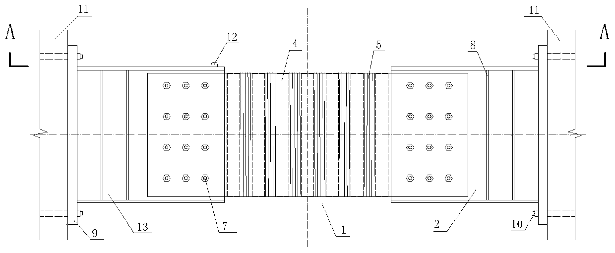
Figure 1 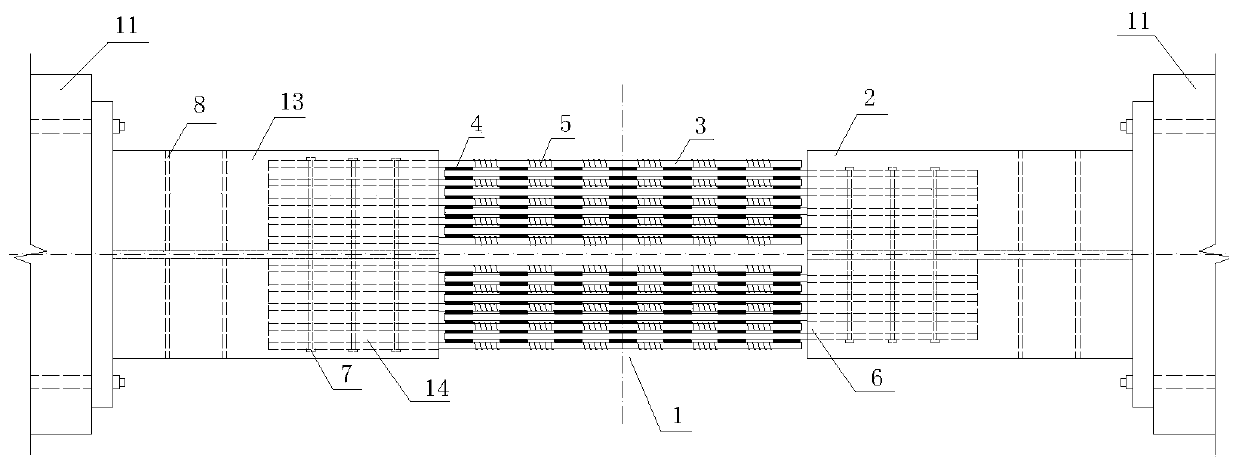
Figure 2 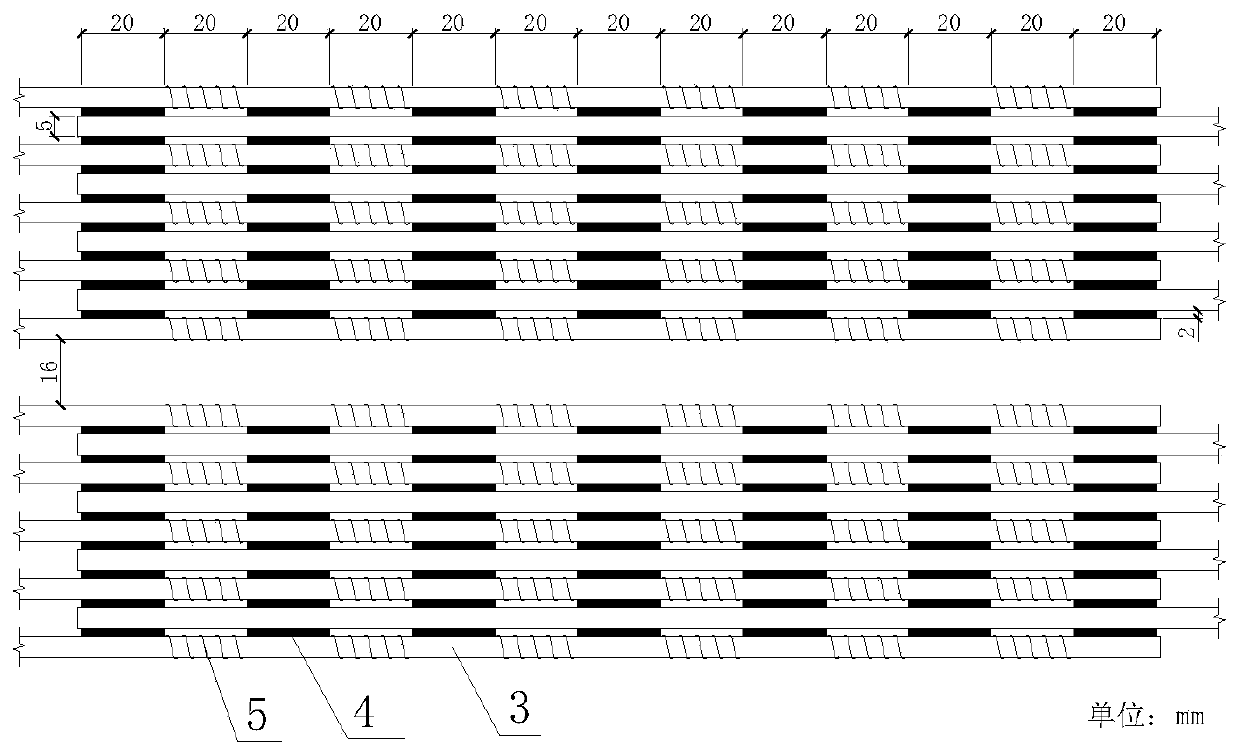
Figure 3
Abstract
Description
technical field
[0001] The invention relates to the field of shock absorption control of building structures, in particular to a coupling beam damper based on a magnetorheological elastomer material.
[0002] technical background
[0003] The frame-shear wall structure is widely used in high-rise building structures, and it has the advantages of flexible spatial arrangement and reasonable stress. In the frame shear wall structure, the shear wall can bear the load transmitted by the horizontal member, and at the same time, because of its large lateral stiffness, it can also resist horizontal earthquake and wind vibration.
[0004] In order to meet the functional requirements of the building, in general projects, vertically arranged door openings are often opened on the shear wall, so that the shear wall is divided into multiple wall piers, and the connecting beams between the openings are shear wall piers. The power transmission member between. Under earthquake action, the c...
Examples
Embodiment Construction
[0028] In order to better understand the present invention, the present invention will be further described below in conjunction with the accompanying drawings and specific embodiments.
[0029] like figure 1 and figure 2 A coupling beam damper based on a magnetorheological elastomer material as shown, including a first H-shaped steel 13 and a second H-shaped steel 2, and a damping device for connecting the first H-shaped steel 13 and the second H-shaped steel 2 1; Specifically, the inner end of the first H-shaped steel 13 / second H-shaped steel 2 is connected to the shock absorbing device 1, and the outer end of the first H-shaped steel 13 / second H-shaped steel 2 is connected to the shear force through the gusset plate 9 respectively. Wall 11 is connected. In this embodiment, the outer ends of the first H-shaped steel 13 and the second H-shaped steel 2 are respectively welded and fixed to one side of the gusset plate 9, and the gusset plate 9 is connected to the shear wall ...