
Adjustable machine tool working lamp
A working light and adjustable technology, which is applied in the direction of the machine power supply, lighting device components, lighting and heating equipment, etc., can solve the problems of poor lighting effect and the need for additional energy supply for machine tool work lights, etc., to achieve good lighting effect Effect
Patent Information
- Authority / Receiving Office
- CN · China
- Current Assignee / Owner
- Publication Date
- 2020-04-17
- Estimated Expiration
- Not applicable · inactive patent
Smart Images
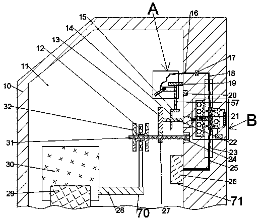
Figure 1 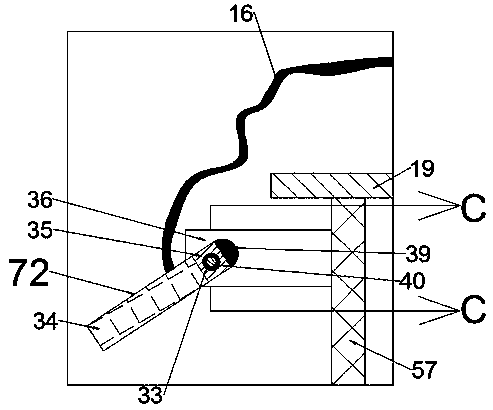
Figure 2 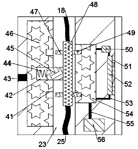
Figure 3
Abstract
Description
technical field
[0001] The invention relates to the field of machine tool accessories, in particular to an adjustable machine tool work light. Background technique
[0002] Machine tool accessories are accessory devices used to expand the processing performance and application range of machine tools. There are many types, among which work lights are the most common and widely used machine tool accessories. Most of the machine tool work lights have a single function, and use external energy to supply energy, which requires additional waste of energy. During the movement of the machine tool table, the position of the machine tool work light cannot be changed, and the lighting effect is poor. Contents of the invention
[0003] The technical problem to be solved by the present invention is to provide an adjustable machine tool work light, which overcomes the need for additional energy supply and poor lighting effect of the machine tool work light.
[0004] The present inventi...
Examples
Embodiment Construction
[0018] Combine below Figure 1-4 The present invention is described in detail, wherein, for the convenience of description, the orientations mentioned below are defined as follows: figure 1 The up, down, left, right, front and back directions of the projection relationship itself are the same.
[0019] combined with Figure 1-4 The adjustable machine tool work light includes a machine tool housing 10, a working chamber 11 is arranged in the machine tool housing 10, a power generating mechanism 70 is arranged in the working chamber 11, and the power generating mechanism 70 includes a Describe the electric guide rail 29 in the working chamber 11, the upper side of the electric guide rail 29 controls a workbench 30, the right end wall of the working chamber 11 is embedded with a generator 21, and the left end surface of the generator 21 is provided with a drive shaft 22. Power generation can be performed in the generator 21 through the rotation of the transmission shaft 22. The...